Mitsubishi Evolution X. Manual - part 213


  Index      Mitsubishi     Mitsubishi Evolution X - service repair manual 2008 year


Search            


Content   ..  211  212  213  214   ..


Mitsubishi Evolution X. Manual - part 213


AUTO-CRUISE CONTROL

TSB Revision

ENGINE AND EMISSION CONTROL

17-21

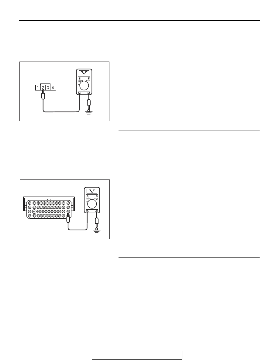
STEP 10. Measure the ground voltage at cruise control 
switch connector C-201 by backprobing.
(1) Do not disconnect cruise control switch connector C-201.
(2) Turn the ignition switch to the "ON" position.
(3) Press the "ON/OFF" switch.

AC601567AD

C-201 Harness connector:
Harness side

(4) Measure the ground voltage between cruise control switch 

connector C-201 terminal number 2 and ground by 
backprobing.

(5) Release the "ON/OFF" switch.
(6) Turn the ignition switch to the "LOCK" (OFF) position.
Q: Is the measured voltage 0.52 volt or less?

YES : Go to Step 17.
NO :  Go to Step 11.

STEP 11. Measure the ground voltage at ECM connector 
B-10.
(1) Remove the ECM [Refer to GROUP 13A, Engine Control 

Module (ECM) 

P.13A-920

].

(2) Connect special tool MB992110 between the ECM and the 

body-side harness connector.

(3) Turn the ignition switch to the "ON" position.
(4) Press the "ON/OFF" switch.

AC709269AB

Special tool 48-pin connector:
Component side

(5) Measure the ground voltage between special tool 48-pin 

connector terminal number 95 (ECM connector B-10 
terminal number 95) and ground.

(6) Release the "ON/OFF" switch.
(7) Turn the ignition switch to the "LOCK" (OFF) position.
(8) Disconnect special tool MB992110 between the ECM and 

the body-side harness connector.

(9) Install the ECM [Refer to GROUP 13A, Engine Control 

Module (ECM) 

P.13A-920

].

Q: Is the measured voltage 0.52 volt or less?

YES : Go to Step 13.
NO :  Go to Step 12.

STEP 12. Check ECM connector B-10 for loose, corroded 
or damaged terminals, or terminals pushed back in the 
connector.
Refer to GROUP 00E, Harness Connector Inspection 

P.00E-2

.

Q: Is the connector and terminals in good condition?

YES : Install the cruise control switch (Refer to 

P.17-69

). 

Then go to Step 19.

NO :  Repair or replace the faulty connector. Install the 

cruise control switch (Refer to 

P.17-69

). Then go to 

Step 21.

AUTO-CRUISE CONTROL

TSB Revision

ENGINE AND EMISSION CONTROL

17-22

STEP 13. Check ECM connector B-10, intermediate 
connector C-130, cruise control switch connector C-201 
and clock spring connectors C-202 and C-205 for loose, 
corroded or damaged terminals, or terminals pushed back 
in the connector.
Refer to GROUP 00E, Harness Connector Inspection 

P.00E-2

.

Q: Is the connectors and terminals in good condition?

YES : Go to Step 14.
NO :  Repair or replace the faulty connector. Install the 

cruise control switch (Refer to 

P.17-69

). Then go to 

Step 21.

STEP 14. Check the harness wire between ECM connector 
B-10 terminal number 95 and cruise control switch 
connector C-201 terminal number 2 for damage.
Q: Is the harness wires in good condition?

YES : Go to Step 15.
NO :  Repair the damaged harness wire. Install the cruise 

control switch (Refer to 

P.17-69

). Then go to Step 21.

STEP 15. Check the clock spring.
Refer to GROUP 52B, Driver’s Air Bag Module Inspection 

P.52B-392

.

Q: Is the clock spring in good condition?

YES : Go to Step 16.
NO :  Replace the clock spring (Refer to GROUP 52B, 

Driver’s Air Bag Module and Clock Spring 

P.52B-386

). Install the cruise control switch (Refer to 

P.17-69

). Then go to Step 21.

STEP 16. Using scan tool MB991958, check data list item 
75: Cancel switch, item 86: Main switch, item 91: Resume 
switch and item 92: Set switch.
(1) Connect scan tool MB991958 to the data link connector 

(Refer to 

P.17-10

).

(2) Turn the ignition switch to the "ON" position.
(3) Set scan tool MB991958 to data reading mode for cruise 

control system (Refer to 

P.17-10

).

• Item 75: Cancel switch.

• When "CANCEL" switch is pressed, the display on 

scan tool MB991958 should be "ON".

• When "CANCEL" switch is released, the display on 

scan tool MB991958 should be "OFF".

• Item 86: Main switch.

• When "ON/OFF" switch is pressed, the display on 

scan tool MB991958 should be "ON".

• When "ON/OFF" switch is pressed again, the display 

on scan tool MB991958 should be "OFF".

AUTO-CRUISE CONTROL

TSB Revision

ENGINE AND EMISSION CONTROL

17-23

• Item 91: Resume switch.

• When "ACC/RES" switch is pressed, the display on 

scan tool MB991958 should be "ON".

• When "ACC/RES" switch is released, the display on 

scan tool MB991958 should be "OFF".

• Item 92: Set switch.

• When "COAST/SET" switch is pressed, the display 

on scan tool MB991958 should be "ON".

• When "COAST/SET" switch is released, the display 

on scan tool MB991958 should be "OFF".

(4) Turn the ignition switch to the "LOCK" (OFF) position.
(5) Disconnect scan tool MB991958.
Q: Is the switch operating properly?

YES : It can be assumed that this malfunction is intermittent 

(Refer to GROUP 00, How to Use 
Troubleshooting/Inspection Service Points 

− How to 

Cope with Intermittent Malfunction 

P.00-15

). Install 

the cruise control switch (Refer to 

P.17-69

).

NO :  Return to Step 2.

STEP 17. Check cruise control switch connector C-201 for 
loose, corroded or damaged terminals, or terminals 
pushed back in the connector.
Refer to GROUP 00E, Harness Connector Inspection 

P.00E-2

.

Q: Is the connector and terminals in good condition?

YES : Go to Step 18.
NO :  Repair or replace the faulty connector. Install the 

cruise control switch (Refer to 

P.17-69

). Then go to 

Step 21.

STEP 18. Check the cruise control switch.
(1) Remove the cruise control switch (Refer to 

P.17-69

).

(2) Check the cruise control switch (Refer to 

P.17-67

).

Q: Is the resistance within specifications?

YES : Install the cruise control switch (Refer to 

P.17-69

). 

Then go to Step 19.

NO :  Replace the cruise control switch (Refer to 

P.17-69

). 

Then go to Step 21.

AUTO-CRUISE CONTROL

TSB Revision

ENGINE AND EMISSION CONTROL

17-24

STEP 19. Using scan tool MB991958, check data list item 
75: Cancel switch, item 86: Main switch, item 91: Resume 
switch and item 92: Set switch.
(1) Connect scan tool MB991958 to the data link connector 

(Refer to 

P.17-10

).

(2) Turn the ignition switch to the "ON" position.
(3) Set scan tool MB991958 to data reading mode for cruise 

control system (Refer to 

P.17-10

).

• Item 75: Cancel switch.

• When "CANCEL" switch is pressed, the display on 

scan tool MB991958 should be "ON".

• When "CANCEL" switch is released, the display on 

scan tool MB991958 should be "OFF".

• Item 86: Main switch.

• When "ON/OFF" switch is pressed, the display on 

scan tool MB991958 should be "ON".

• When "ON/OFF" switch is pressed again, the display 

on scan tool MB991958 should be "OFF".

• Item 91: Resume switch.

• When "ACC/RES" switch is pressed, the display on 

scan tool MB991958 should be "ON".

• When "ACC/RES" switch is released, the display on 

scan tool MB991958 should be "OFF".

• Item 92: Set switch.

• When "COAST/SET" switch is pressed, the display 

on scan tool MB991958 should be "ON".

• When "COAST/SET" switch is released, the display 

on scan tool MB991958 should be "OFF".

(4) Turn the ignition switch to the "LOCK" (OFF) position.
(5) Disconnect scan tool MB991958.
Q: Is the switch operating properly?

YES : Go to Step 20.
NO :  Replace the ECM [Refer to GROUP 13A, Engine 

Control Module (ECM) 

P.13A-920

]. When the ECM is 

replaced, register the encrypted code (Refer to 
GROUP 42C, Diagnosis 

− ID Code Registration 

Judgment Table 

P.42C-9

). Then go to Step 21.


Content   ..  211  212  213  214   ..