Mitsubishi Evolution X. Manual - part 212


  Index      Mitsubishi     Mitsubishi Evolution X - service repair manual 2008 year


Search            


Content   ..  210  211  212  213   ..


Mitsubishi Evolution X. Manual - part 212


AUTO-CRUISE CONTROL

TSB Revision

ENGINE AND EMISSION CONTROL

17-17

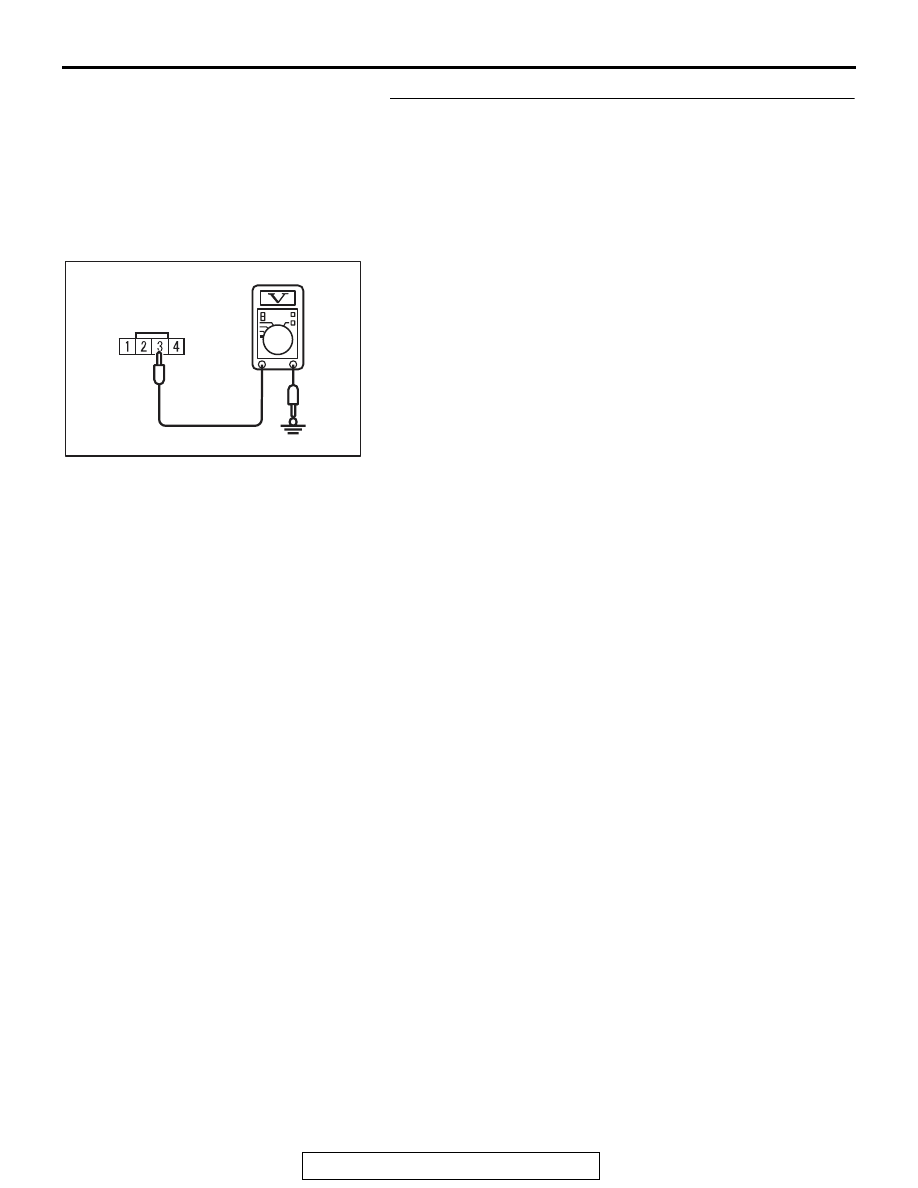
STEP 2. Measure the power supply voltage at cruise 
control switch connector C-201 by backprobing.
(1) With the harness connector, remove the cruise control 

switch (Refer to 

P.17-69

).

(2) Connect the negative (

−) battery cable.

(3) Do not disconnect cruise control switch connector C-201.
(4) Turn the ignition switch to the "ON" position.
(5) Do not operate the cruise control switch.

AC601563 AD

C-201 Harness connector:
Harness side

(6) Measure the power supply voltage between cruise control 

switch connector C-201 terminal number 3 and ground by 
backprobing.

(7) Turn the ignition switch to the "LOCK" (OFF) position.
Q: Is the measured voltage between 4.7 and 5.0 volts?

YES : Go to Step 10.
NO :  Go to Step 3.

AUTO-CRUISE CONTROL

TSB Revision

ENGINE AND EMISSION CONTROL

17-18

STEP 3. Measure the power supply voltage at ECM 
connector B-10.
(1) Remove the ECM [Refer to GROUP 13A, Engine Control 

Module (ECM) 

P.13A-920

].

AC709266AB

82 81 80 79 78 77 76 75 74 73 72 71

94 93 92 91 90 89 88 87 86 85 84 83

99 98 97 96 95

100

101

102

103

104

105

106

112

113

114

109 108

107

110

111

115

116

117

118

MB992110

ECM

B-10 (GR)

Special tool 48-pin connector

(2) Connect special tool MB992110 between the ECM and the 

body-side harness connector.

(3) Turn the ignition switch to the "ON" position.
(4) Do not operate the cruise control switch.

AC709268AB

Special tool 48-pin connector:
Component side

(5) Measure the power supply voltage between special tool 

48-pin connector terminal number 107 (ECM connector 
B-10 terminal number 107) and ground.

(6) Turn the ignition switch to the "LOCK" (OFF) position.
(7) Disconnect special tool MB992110 between the ECM and 

the body-side harness connector.

(8) Install the ECM [Refer to GROUP 13A, Engine Control 

Module (ECM) 

P.13A-920

].

Q: Is the measured voltage between 4.7 and 5.0 volts?

YES : Go to Step 6.
NO :  Go to Step 4.

STEP 4. Check ECM connector B-10 for loose, corroded or 
damaged terminals, or terminals pushed back in the 
connector.
Refer to GROUP 00E, Harness Connector Inspection 

P.00E-2

.

Q: Is the connector and terminals in good condition?

YES : Go to Step 5.
NO :  Repair or replace the faulty connector. Install the 

cruise control switch (Refer to 

P.17-69

). Then go to 

Step 21.

AUTO-CRUISE CONTROL

TSB Revision

ENGINE AND EMISSION CONTROL

17-19

STEP 5. Check the harness for short circuit to ground 
between the ECM connector B-10 terminal number 107 and 
the cruise control switch connector C-201 terminal number 
3.
(1) Disconnect ECM connector B-10 and measure at the 

harness connector side.

(2) Turn the ignition switch to the "LOCK" (OFF) position.

AC601566 AD

B-10 Harness connector:
Component side

(3) Measure the continuity between ECM connector B-10 

terminal number 107 and ground.

(4) Reconnect ECM connector B-10.
Q: Is the measured continuity open circuit?

YES : Install the cruise control switch (Refer to 

P.17-69

). 

Then go to Step 19.

NO :  Go to Step 6.

STEP 6. Check intermediate connector C-130, cruise 
control switch connector C-201 and clock spring 
connectors C-202 and C-205 for loose, corroded or 
damaged terminals, or terminals pushed back in the 
connector.
Refer to GROUP 00E, Harness Connector Inspection 

P.00E-2

.

Q: Is the connectors and terminals in good condition?

YES : Go to Step 7.
NO :  Repair or replace the faulty connector. Install the 

cruise control switch (Refer to 

P.17-69

). Then go to 

Step 21.

STEP 7. Check the harness wire between ECM connector 
B-10 terminal number 107 and cruise control switch 
connector C-201 terminal number 3 for damage.
Q: Is the harness wires in good condition?

YES : Go to Step 8.
NO :  Repair the damaged harness wire. Install the cruise 

control switch (Refer to 

P.17-69

). Then go to Step 21.

STEP 8. Check the clock spring.
Refer to GROUP 52B, Driver’s Air Bag Module Inspection 

P.52B-392

.

Q: Is the clock spring in good condition?

YES : Go to Step 9.
NO :  Replace the clock spring (Refer to GROUP 52B, 

Driver’s Air Bag Module and Clock Spring 

P.52B-386

). Install the cruise control switch (Refer to 

P.17-69

). Then go to Step 21.

AUTO-CRUISE CONTROL

TSB Revision

ENGINE AND EMISSION CONTROL

17-20

STEP 9. Using scan tool MB991958, check data list item 75: 
Cancel switch, item 86: Main switch, item 91: Resume 
switch and item 92: Set switch.
(1) Connect scan tool MB991958 to the data link connector 

(Refer to 

P.17-10

).

(2) Turn the ignition switch to the "ON" position.
(3) Set scan tool MB991958 to data reading mode for cruise 

control system (Refer to 

P.17-10

).

• Item 75: Cancel switch.

• When "CANCEL" switch is pressed, the display on 

scan tool MB991958 should be "ON".

• When "CANCEL" switch is released, the display on 

scan tool MB991958 should be "OFF".

• Item 86: Main switch.

• When "ON/OFF" switch is pressed, the display on 

scan tool MB991958 should be "ON".

• When "ON/OFF" switch is pressed again, the display 

on scan tool MB991958 should be "OFF".

• Item 91: Resume switch.

• When "ACC/RES" switch is pressed, the display on 

scan tool MB991958 should be "ON".

• When "ACC/RES" switch is released, the display on 

scan tool MB991958 should be "OFF".

• Item 92: Set switch.

• When "COAST/SET" switch is pressed, the display 

on scan tool MB991958 should be "ON".

• When "COAST/SET" switch is released, the display 

on scan tool MB991958 should be "OFF".

(4) Turn the ignition switch to the "LOCK" (OFF) position.
(5) Disconnect scan tool MB991958.
Q: Is the switch operating properly?

YES : It can be assumed that this malfunction is intermittent 

(Refer to GROUP 00, How to Use 
Troubleshooting/Inspection Service Points 

− How to 

Cope with Intermittent Malfunction 

P.00-15

). Install 

the cruise control switch (Refer to 

P.17-69

).

NO :  Return to Step 2.


Content   ..  210  211  212  213   ..