Mitsubishi Evolution X. Manual - part 188


  Index      Mitsubishi     Mitsubishi Evolution X - service repair manual 2008 year


Search            


Content   ..  186  187  188  189   ..


Mitsubishi Evolution X. Manual - part 188


ENGINE ASSEMBLY

TSB Revision

ENGINE MECHANICAL

11A-83

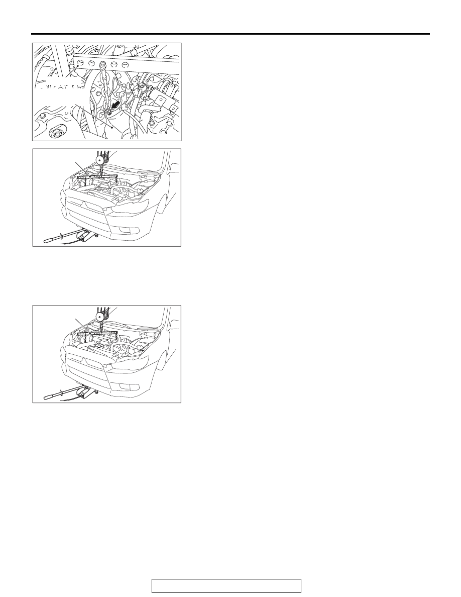
3. Set special tool MB991454 to the engine hanger and the 

power steering oil pump bracket.

4. Hold the engine assembly with a chain block.
5. Place a garage jack against the engine oil pan with a piece 

of wood in between, and remove the engine mounting 
bracket while adjusting the position of the engine.

6. After checking that all cables, hoses and wiring harness 

connectors and so on are disconnected from the engine, lift 
the engine assembly slowly with the chain block to remove 
the engine assembly upward from the engine compartment.

INSTALLATION SERVICE POINTS

.

>>A<< ENGINE ASSEMBLY/ENGINE MOUNTING 
BRACKET INSTALLATION

1. Set special tool MB991454 and a chain block to the engine 

assembly.

2. Install the engine assembly, being careful not to pinch the 

cables, hoses or wiring harness connectors.

3. Place a garage jack against the engine oil pan with a piece 

of wood in between, and install the engine mounting bracket 
while adjusting the position of the engine.

4. Remove the chain block.

AC706145AC

MB991454

Power steering
oil pump bracket

AC704732

MB991454

AC

AC704732

MB991454

AC

ENGINE ASSEMBLY

TSB Revision

ENGINE MECHANICAL

11A-84

5. Install special tool MB991928 or MB991895 which is used 

during installation of transaxle assembly to hold the engine 
assembly. (Refer to GROUP 22A, Transaxle Assembly 

P.22A-127

<M/T>), (Refer to GROUP 22C, Transaxle 

Assembly 

P.22C-341

<TC-SST>)

.

>>B<< A/C COMPRESSOR AND CLUTCH 
ASSEMBLY INSTALLATION

Tighten A/C compressor and clutch assembly mounting bolts to 
the specified torque in the order of number shown in the illus-
tration.

Tightening torque: 23 

± 6 N⋅ m (17 ± 4 ft-lb)

AC706008AD

MB991928

MB992201

AC706009 AD

MB991895

MB992201

AC506759

AE

1

2

3

A/C compressor 
and clutch assembly

11B-1

GROUP 11B

ENGINE OVERHAUL

CONTENTS

GENERAL SPECIFICATIONS . . . . . .

11B-2

SERVICE SPECIFICATIONS. . . . . . .

11B-2

FASTENER TIGHTENING 


SPECIFICATIONS . . . . . . . . . . . . . . .

11B-4

SEALANTS AND ADHESIVES . . . . .

11B-7

SPECIAL TOOLS. . . . . . . . . . . . . . . .

11B-8

GENERATOR AND IGNITION 


SYSTEM . . . . . . . . . . . . . . . . . . . . . . .

11B-10

REMOVAL AND INSTALLATION . . . . . . . . 

11B-10

THROTTLE BODY . . . . . . . . . . . . . . .

11B-14

REMOVAL AND INSTALLATION . . . . . . . . 

11B-14

INTAKE MANIFOLD AND FUEL 


SYSTEM . . . . . . . . . . . . . . . . . . . . . . .

11B-16

REMOVAL AND INSTALLATION . . . . . . . . 

11B-16

EXHAUST MANIFOLD. . . . . . . . . . . .

11B-20

REMOVAL AND INSTALLATION . . . . . . . . 

11B-20

WATER HOSE AND PIPE . . . . . . . . .

11B-24

REMOVAL AND INSTALLATION . . . . . . . . 

11B-24

OIL PAN AND TIMING CHAIN 


CASE. . . . . . . . . . . . . . . . . . . . . . . . . .

11B-27

REMOVAL AND INSTALLATION  . . . . . . . . 

11B-27

TIMING CHAIN . . . . . . . . . . . . . . . . . .

11B-34

REMOVAL AND INSTALLATION  . . . . . . . . 

11B-34

INSPECTION. . . . . . . . . . . . . . . . . . . . . . . . 

11B-39

CAMSHAFT  . . . . . . . . . . . . . . . . . . . .

11B-41

REMOVAL AND INSTALLATION  . . . . . . . . 

11B-41

INSPECTION. . . . . . . . . . . . . . . . . . . . . . . . 

11B-44

CYLINDER HEAD AND VALVES. . . .

11B-47

REMOVAL AND INSTALLATION  . . . . . . . . 

11B-47

INSPECTION. . . . . . . . . . . . . . . . . . . . . . . . 

11B-52

OIL PUMP CHAIN. . . . . . . . . . . . . . . .

11B-56

REMOVAL AND INSTALLATION  . . . . . . . . 

11B-56

INSPECTION. . . . . . . . . . . . . . . . . . . . . . . . 

11B-61

PISTON AND CONNECTING ROD  . .

11B-62

REMOVAL AND INSTALLATION  . . . . . . . . 

11B-62

INSPECTION. . . . . . . . . . . . . . . . . . . . . . . . 

11B-70

CRANKSHAFT AND CYLINDER 


BLOCK . . . . . . . . . . . . . . . . . . . . . . . .

11B-71

REMOVAL AND INSTALLATION  . . . . . . . . 

11B-71

INSPECTION. . . . . . . . . . . . . . . . . . . . . . . . 

11B-76

GENERAL SPECIFICATIONS

TSB Revision

ENGINE OVERHAUL

11B-2

GENERAL SPECIFICATIONS

M1113000201891

Descriptions

Specifications

Engine model

4B11

Type

In line OHV, DOHC

Number of cylinders

4

Combustion chamber

Pent-roof type

Total displacement cm

3

 (cu in)

1,998 (121.9)

Cylinder bore mm (in)

86 (3.4)

Piston stroke mm (in)

86 (3.4)

Compression ratio

9.0

Valve timing

Intake valve

Opens

10

°  BTDC − 35°  BTDC

Closes

62

°  ABDC − 37°  ABDC

Exhaust valve

Open

44

°  BBDC − 9°  BBDC

Close

0

°  ATDC − 35°  ATDC

Auto lash adjuster

Non-equipped

SERVICE SPECIFICATIONS

M1113000302169

Item

Standard value

Limit

Timing chain
Valve clearance mm (in)

Intake

0.20 

± 0.03 (0.008 ± 0.001) −

Exhaust

0.30 

± 0.03 (0.012 ± 0.001) −

Camshaft
Cam height of camshaft mm (in)

Intake

44.1 (1.74)

43.6 (1.72)

Exhaust

45.0 (1.77)

44.5 (1.75)

Camshaft oil clearance mm (in)

0.035 

− 0.072

(0.0014 

− 0.0028)

Cylinder head and valves
Distortion of cylinder head bottom mm (in)

Within 0.05 (0.002)

0.2 (0.01)

Grinding limit of cylinder head bottom mm (in)

0.2 (0.01)

Overall height of cylinder head mm (in)

128.5 (5.06)

Overall length of valve mm (in)

Intake

113.18 (4.456)

112.68 (4.436)

Exhaust

105.89 (4.169)

105.39 (4.149)

Valve margin mm (in)

Intake

1.022 (0.0402)

0.522 (0.0206)

Exhaust

1.094 (0.0431)

0.594 (0.0234)

Free height of valve spring mm (in)

51.5 (2.03)

51.0 (2.01)

Squareness of valve spring

2

°  or less

4

°


Content   ..  186  187  188  189   ..