Mitsubishi Evolution X. Manual - part 186


  Index      Mitsubishi     Mitsubishi Evolution X - service repair manual 2008 year


Search            


Content   ..  184  185  186  187   ..


Mitsubishi Evolution X. Manual - part 186


TIMING CHAIN

TSB Revision

ENGINE MECHANICAL

11A-75

INSTALLATION SERVICE POINTS

.

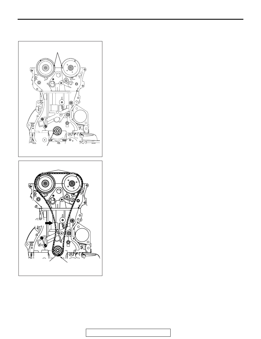
>>A<< TIMING CHAIN INSTALLATION

1. Set the timing marks of the camshaft sprockets and the 

crankshaft sprocket as shown in the figure.

2. Align each sprocket timing chain mating mark with the link 

plate (blue) of timing chain to avoid slack of the timing chain 
tension side, and install the timing chain to the sprockets.

.

AC710641

AB

Camshaft sprocket
timing marks

Crankshaft sprocket
timing mark

AC506772

AP

Tension side

Link plates (blue)

Link plate (blue)

Mating 
mark

Mating 
mark

Mating mark

TIMING CHAIN

TSB Revision

ENGINE MECHANICAL

11A-76

>>B<< TIMING CHAIN TENSIONER 
INSTALLATION

1. Check that the sprocket timing chain mating marks align 

with the link plates (blue) of the timing chain, and install the 
timing chain tensioner to the cylinder block. 

2. Remove the hard wire or L-shaped hexagon wrench fixing 

the plunger of the timing chain tensioner to apply tension to 
the timing chain.

.

>>C<< CRANKSHAFT FRONT OIL SEAL 
INSTALLATION

1. Apply a small amount of engine oil to the entire inner 

diameter of the oil seal lip.

CAUTION

When installing the crankshaft oil seal, be careful to avoid 
damage to the crankshaft front oil seal.
2. Using special tool MB991448, press in the crankshaft front 

oil seal up to the chamfered surface of timing chain case.

AC506772

AQ

Link plates (blue)

Link plate (blue)

Mating 
mark

Mating 
mark

Mating mark

AC506773

AE

Timing chain 
tensioner

Hard wire or 
L-shaped 
hexagon 
wrench

AC506763 AC

MB991448

Timing chain case

TIMING CHAIN

TSB Revision

ENGINE MECHANICAL

11A-77

.

>>D<< TIMING CHAIN CASE ASSEMBLY 
INSTALLATION

CAUTION

• Be sure to remove the sealant remaining in the mount-

ing hole, O-ring groove, and gap between parts.

• Use the quick-drying degreasing agent (white gasoline) 

to degrease, then check that no grease is remaining on 
the sealant application area.

• After degreasing with the quick-drying degreasing 

agent (white gasoline), never touch the degreased area 
with fingers.

1. Remove all the traces of sealant adhering to the timing chain 

case assembly installation surfaces of timing chain case 
assembly, cylinder block, and cylinder head. Then, 
degrease the surfaces with the quick-drying degreasing 
agent (white gasoline).

2. Remove all the sealant adhering to the gasket between the 

cylinder head and cylinder block (three-surface aligned 
part). Then, degrease the surfaces with the quick-drying 
degreasing agent (white gasoline).

3. As for the three-surface aligned part that is indicated in Step 

2 above, the engine oil oozes from the cylinder head gasket. 
Thus, quickly apply the sealant to it after degreasing.

TIMING CHAIN

TSB Revision

ENGINE MECHANICAL

11A-78

4. To the timing chain case assembly mating surface, apply the 

sealant with a width of 2.5 

± 0.5 mm (0.1 ± 0.02 inch) and 

without a gap. However, with the "A" shown in the figure, 
apply the sealant with overlapping the diameter of 4.5 

± 0.5 

mm (0.18 

± 0.02 inch) or 2.5 ± 0.5 mm (0.1 ± 0.02 inch) as 

shown in the figure.

Specified sealant: Three bond 1217G

CAUTION

• If the sealant contacts any other part during installation 

of the timing chain case assembly, apply sealant again 
before installing the timing chain case assembly.

• Within two hours after the timing chain case assembly 

installation, do not apply oil or water to the sealant 
application area or start the engine.

5. Within three minutes after the application of sealant, install 

the timing chain case assembly to the cylinder block and 
cylinder head so that the sealant does not contact other 
parts.

6. To the installation positions shown in the figure, tighten the 

timing chain case assembly mounting bolts to the specified 
torque shown below.

.

Bolt (symbol)

Thread 
diameter x 
Length mm

Tightening torque

Flange bolt (A) M6 

×  25

10 

± 2 N⋅ m (89 ± 

17 in-lb)

Flange bolt (B) M8 

×  28

24 

± 4 N⋅ m (18 ± 2 

ft-lb)

Bolt (C)

M6 

×  25

10 

± 2 N⋅ m (89 ± 

17 in-lb)

AC708935

φ 4.5 ± 0.5 mm
(

φ 0.18 ± 0.02 in)

4.5 ± 0.5 mm
(0.18 ± 0.02 in)

  3 ± 0.5 mm
(0.12 ± 0.02 in)

2.5 mm
(0.1 in)

φ 2.5 ± 0.5 mm
(

φ 0.1 ± 0.02 in)

φ 2.5 ± 0.5 mm
(

φ 0.1 ± 0.02 in)

φ 2.5 ± 0.5 mm
(

φ 0.1 ± 0.02 in)

3 ± 0.5 mm
(0.12 ± 0.02 in)

φ 2.5 ± 0.5 mm
(

φ 0.1 ± 0.02 in)

7.5 ± 0.5 mm
(0.30 ± 0.02 in)

1 ± 0.5 mm
(0.04 ± 0.02 in)

A

A

A

A

A

B

B

A

C

C

Section A – A

Section B – B

Section C – C

AB

AC708525AC

A

A

A

A

A

A

B

B

B

B

B

B

C


Content   ..  184  185  186  187   ..