Mitsubishi Evolution X. Manual - part 173


  Index      Mitsubishi     Mitsubishi Evolution X - service repair manual 2008 year


Search            


Content   ..  171  172  173  174   ..


Mitsubishi Evolution X. Manual - part 173


CRANKSHAFT PULLEY

TSB Revision

ENGINE MECHANICAL

11A-23

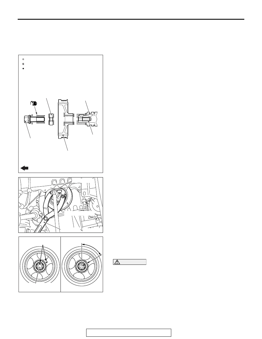
INSTALLATION SERVICE POINTS

.

>>A<< CRANKSHAFT PULLEY/CRANKSHAFT 
PULLEY WASHER/CRANKSHAFT PULLEY CEN-
TER BOLT INSTALLATION

1. Wipe off the dirt on the crankshaft and the crankshaft pulley 

as shown in the figure using a rag.

2. Wipe off the dirt on the crankshaft sprocket, the crankshaft 

and the crankshaft pulley as shown in the figure using a rag, 
and then degrease them.
NOTE: Degrease them to prevent drop in the friction coeffi-
cient of the pressed area, which is caused by oil adhesion.

3. Install the crankshaft pulley.
4. Wipe off the dirt on the crankshaft pulley washer and the 

crankshaft pulley center bolt as shown in the figure using a 
rag.

5. Apply an adequate and minimum amount of engine oil to the 

threads of the crankshaft pulley center bolt and the lower 
area of the flange.

6. Hold the crankshaft pulley with special tools MB990767 and 

MD998719 in the same manner as removal.

7. Tighten the crankshaft pulley center bolt according to the 

following procedure.

(1) Tighten the crankshaft pulley center bolt to the specified 

torque 250 N

⋅ m (184 ft-lb).

(2) Loosen the crankshaft pulley center bolt fully.
(3) Tighten the crankshaft pulley center bolt to the specified 

torque 110 N

⋅ m (81 ft-lb).

(4) As shown in the illustration "A," apply the paint mark to 

the crankshaft pulley on the extended line of the corner 
adjacent to the one of the crankshaft pulley center bolt 
corners.

CAUTION

• When the tightening angle is smaller than the specified 

tightening angle, the appropriate tightening capacity 
cannot be secured.

• When the tightening angle is larger than the specified 

tightening angle, remove the bolt to start from the 
beginning again according to the procedure.

(5) Tighten the crankshaft pulley center bolt by 60

°  once 

more. Make sure the paint mark of crankshaft pulley 
center bolt is aligned with the paint mark of crankshaft 
pulley as shown in the illustration "B."

.

AC705007

AC

: Wipe clean with a rag.
: Wipe clean with a rag and degrease.
: Apply a small amount of engine oil.

Crankshaft
pulley center bolt

Crankshaft
pulley washer

Crankshaft
pulley

Crankshaft

Crankshaft
sprocket

Engine front

AC506738

AC

MB990767

MD998719

Crankshaft pulley

AC710640AB

A

B

60˚

Paint mark

Crankshaft pulley
center bolt

CRANKSHAFT PULLEY

TSB Revision

ENGINE MECHANICAL

11A-24

>>B<< DRIVE BELT INSTALLATION

CAUTION

• To reuse the drive belt, install it by aligning the arrow 

mark on the backside of belt marked at the removal 
with the rotating direction.

• Check that the notches of the notched pulley and the 

notches of the drive belt are fit correctly.

• Check that the drive belt is installed in the center of the 

flat surface of the flat pulley.

1. Install the drive belt to each pulley as shown in the figure.

2. Set an offset wrench [45 

° , a long offset wrench (5/8 x 11/16 

inches) recommended] to the pulley bolt of the 
auto-tensioner. Then, rotate the auto-tensioner 
counterclockwise and remove the L-shaped hexagon 
wrench fixing the auto-tensioner.

3. Apply tension to the drive belt while slowly turning the 

auto-tensioner clockwise. 

AC704717AG

Drive belt

Notched pulley

Flat pulley

AC706172

AC

Generator

Crankshaft 
pulley

Water pump
pulley

AC706600AC

Auto-tensioner

L-shaped 
hexagon 
wrench

CAMSHAFT

TSB Revision

ENGINE MECHANICAL

11A-25

CAMSHAFT

REMOVAL AND INSTALLATION

M1112007800508

Pre-removal operation
• Engine Room Under Cover Front A, B and Engine Room 

Side Cover (RH) Removal (Refer to GROUP 51, Under 

Cove

P.51-16

).

• Air Cleaner Assembly Removal (Refer to GROUP 15, Air 

Cleane

P.15-10

).

• Charge Air Cooler Intake Hose A, B and Charge Air 

Cooler Intake Pipe A Removal (Refer to GROUP 15, 

Charge Air Cooler 

P.15-15

).

• Strut Tower Bar Removal (Refer to GROUP 42A, Strut 

Tower Bar 

P.42A-15

).

• Ignition Coil Removal (Refer to GROUP 16, Ignition Sys-

tem 

− Ignition Coil 

P.16-39

).

Post-installation operation
• Ignition Coil Installation (Refer to GROUP 16, Ignition 

System 

− Ignition Coil 

P.16-39

).

• Strut Tower Bar Installation (Refer to GROUP 42A, Strut 

Tower Bar 

P.42A-15

).

• Charge Air Cooler Intake Hose A, B and Charge Air 

Cooler Intake Pipe A Installation (Refer to GROUP 15, 

Charge Air Cooler 

P.15-15

).

• Air Cleaner Assembly Installation (Refer to GROUP 15, 

Air Cleaner 

P.15-10

).

• Engine Room Under Cover Front A, B and Engine Room 

Side Cover (RH) Installation (Refer to GROUP 51, Under 

Cover 

P.51-16

).

CAMSHAFT

TSB Revision

ENGINE MECHANICAL

11A-26

AC708206

1

23

17

16

13

9

20

6

2

AC

85 ± 5 N·m
63 ± 4 ft-lb

7

19

3

31

30

22

11

14

15

24

25

26

29

28

5

34

25 ± 4 N·m
18 ± 3 ft-lb

32

N

35

N

10

13 ± 1 N·m
115 ± 9 in-lb

12

21

4

33

8

N

18

27

N

N

Apply engine oil to all
moving parts before
installation.

10 ± 2 N·m
89 ± 17 in-lb

12 ± 1 N·m
107 ± 8 in-lb  

17 ± 3 N·m
13 ± 2 ft-lb

3.0 ± 1.0 N·m
27 ± 8 in-lb

to

30 ± 2 N·m
23 ± 1 ft-lb

to

5.5 ± 0.5 N·m
49 ± 4 in-lb

12 ± 1 N·m
107 ± 8 in-lb  

10 ± 2 N·m
89 ± 17 in-lb

10 ± 2 N·m
89 ± 17 in-lb

10 ± 2 N·m
89 ± 17 in-lb

10 ± 2 N·m
89 ± 17 in-lb

(Engine oil)

(Engine oil)

Camshaft removal steps 

1.

Breather hose connection

2.

PCV hose connection

3.

Power steering fluid pressure 
switch connector connection

4.

Intake oil feeder control valve 
connector connection

5.

Exhaust oil feeder control valve 
connector connection

6.

Control harness connection

<<

A

>>

>>

G

<<

7.

Rocker cover assembly

8.

Rocker cover gasket

<<

B

>>

Cylinder No. 1 compression top 
dead center setting (only at 
removal)

Valve clearance adjustment 
(Refer to 

P.11A-10

). (only at 

installation)

9.

Timing chain upper guide

10. Service hole bolt

<<

C

>>

Camshaft and camshaft sprocket 
assembly (exhaust side) removal 
preparatory operation (only at 
removal)

Camshaft removal steps 


Content   ..  171  172  173  174   ..