Mitsubishi Evolution X. Manual - part 171


  Index      Mitsubishi     Mitsubishi Evolution X - service repair manual 2008 year


Search            


Content   ..  169  170  171  172   ..


Mitsubishi Evolution X. Manual - part 171


ON-VEHICLE SERVICE

TSB Revision

ENGINE MECHANICAL

11A-15

CAUTION

To prevent damage to scan tool MB991958, always turn the 
ignition switch to the "LOCK" (OFF) position before con-
necting or disconnecting scan tool MB991958.
11.Disconnect scan tool MB991958 from the data link 

connector.

COMPRESSION PRESSURE CHECK

M1111002602278

Required Special Tool:
MB991958: Scan Tool (M.U.T.-III Sub Assembly)

• MB991824: V.C.I.

• MB991827: M.U.T.-III USB Cable

• MB991910: M.U.T.-III Main Harness A

1. Before inspection, check that the engine oil, starter and 

battery are normal. Also, set the vehicle in the following 
condition:

• Engine coolant temperature: 80 − 95° C (176 − 203° F)

• Lights and all accessories: OFF

• Transaxle: Neutral (P range on vehicles with TC-SST)

NOTE: On vehicles for Canada, the headlight, taillight, etc. 
remain lit even when the lighting switch is in "OFF" position 
but this is no problem for checks.

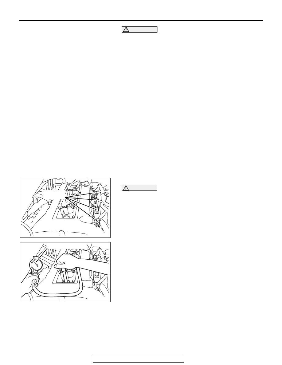
2. Remove all of the ignition coils and spark plugs.
3. Disconnect the all of the injector connectors.

WARNING

Keep your distance from the spark plug hole when 
cranking. Oil, fuel, etc., may spray out from the spark 
plug hole and may cause serious injury.

4. Cover the spark plug hole with a shop towel etc., after the 

engine has been cranked, check that no foreign material is 
adhering to the shop towel.

5. Set compression gauge to one of the spark plug holes.
6. Crank the engine with the throttle valve fully open and 

measure the compression pressure.

Standard value (at engine speed of 200 r/min): 1,090 

kPa (158 psi)

Limit (at engine speed of 200 r/min): Minimum 650 

kPa (95 psi)

7. Measure the compression pressure for all the cylinders, and 

check that the pressure differences of the cylinders are 
below the limit.

Limit: Maximum 100 kPa (14 psi)

8. If there is a cylinder with compression or a compression 

difference that is outside the limit, pour a small amount of 
engine oil through the spark plug hole, and repeat the 
operations in steps from 5 to 7.

AK502603AE

Injector 
connectors

AK502604AE

Compression gauge

ON-VEHICLE SERVICE

TSB Revision

ENGINE MECHANICAL

11A-16

(1) If the compression increases after oil is added, the cause 

of the malfunction is a worn or damaged piston ring 
and/or cylinder inner surface.

(2) If the compression does not rise after oil is added, the 

cause is a burnt or defective valve seat, or pressure is 
leaking from the gasket.

9. Connect the all of the injector connector.
10.Install the spark plugs and ignition coils.
11.Use the scan tool MB991958 to erase the diagnosis codes.

NOTE: This will erase the diagnosis code resulting from the 
injector connectors being disconnected.

MANIFOLD VACUUM CHECK

M1111002701711

Required Special Tool:
MB991958: Scan Tool (M.U.T.-III Sub Assembly)

• MB991824: V.C.I.

• MB991827: M.U.T.-III USB Cable

• MB991910: M.U.T.-III Main Harness A

1. Before inspection, set the vehicle in the following condition:

• Engine coolant temperature: 80 − 95° C (176 − 203° F)

• Lights and all accessories: OFF

• Transaxle: Neutral (P range on vehicles with TC-SST)

NOTE: On vehicles for Canada, the headlight, taillight, etc. 
remain lit even when the lighting switch is in "OFF" position 
but this is no problem for checks.

AC608435

Data link connector

MB991827

MB991824

MB991910

AB

ON-VEHICLE SERVICE

TSB Revision

ENGINE MECHANICAL

11A-17

CAUTION

To prevent damage to scan tool MB991958, always turn the 
ignition switch to the "LOCK" (OFF) position before con-
necting or disconnecting scan tool MB991958.
2. Connect scan tool MB991958 to the data link connector.

3. Disconnect the ventilation hose from the positive crankcase 

ventilation (PCV) valve, and then connect a vacuum gauge 
to the ventilation hose. Plug the PCV valve.

4. Start the engine and check that idle speed is approximately 

700 r/min.

5. Check the intake manifold vacuum.

Limit: Minimum 60 kPa (18 in Hg)

6. Turn off the ignition switch.
7. Remove the vacuum gauge and then connect the ventilation 

hose to the PCV valve.

CAUTION

To prevent damage to scan tool MB991958, always turn the 
ignition switch to the "LOCK" (OFF) position before con-
necting or disconnecting scan tool MB991958.
8. Disconnect scan tool MB991958 from the data link 

connector.

TIMING CHAIN ELONGATION VISUAL CHECK

M1111005200024

NOTE: When the timing chain elongates more than the speci-
fied length, the diagnosis code No. P0012, variable valve tim-
ing (VVT) advanced-angle value abnormal, is output. Unless 
the diagnosis code No. P0012, therefore, is output, the visual 
check is unnecessary. 
NOTE: Unless the work using the following scan tool 
MB991958 is correctly carried out due to the malfunction of 
ECM, carry out the check whether or not the diagnosis code 
exists.

.

AC608435

Data link connector

MB991827

MB991824

MB991910

AB

AK502601AE

Plug

PCV valve

Vacuum gauge

ON-VEHICLE SERVICE

TSB Revision

ENGINE MECHANICAL

11A-18

Storing the learning value regarding the amount of timing 
chain elongation before the ECM replacement

Writing the learning value into the new ECM after the ECM 
replacement

1. Remove all the ignition coils.
2. Remove the cylinder head cover.
3. Remove the upper chain guide.

CAUTION

Always rotate the crankshaft clockwise.
4. Rotating the crankshaft clockwise, align the timing mark of 

camshaft sprocket with the point on the upper plane of 
cylinder head shown in the illustration. As a result of this, the 
No.1 cylinder is positioned at the compression TDC.

5. Look at the inside of timing chain case with one eye in the 

direction of arrow shown in the illustration. Fix the eye line at 
the point where the top axis line of the chain elongation 
indicator at the front side of timing chain case is overlapped 
with that of the chain elongation indicator at the reverse side 
of timing chain case.

AK604565

Timing mark

AF

Timing chain case

AK703387AC

Visual line (visual axis)

Chain elongation
indicator


Content   ..  169  170  171  172   ..