Mitsubishi Evolution X. Manual - part 153
CONSTRUCTION DESCRIPTION
TSB Revision
FOUR-WHEEL ANTI-LOCK BRAKE SYSTEM (4ABS)
35B-7
ASC-ECU
M2351003000713
• This ECU incorporates the ABS function, EBD
function, ASC function, and TCL function.
• By integrating ABS-ECU into the hydraulic unit,
no more wiring harnesses for sending signal that
operates the solenoid valve and pump motor is
required, assuring higher reliability.
• Self-diagnostic and memory functions are inte-
grated into ASC-ECU. If any malfunction is
detected by the diagnostic function, ABS-ECU
activates a fail-safe function and illuminates the
ABS warning light and brake warning light
*
.
NOTE:
*
: The brake warning light is used as the
EBD control warning light.
• ASC-ECU detects the vehicle deceleration speed
using the signals of the steering wheel sensor,
wheel speed sensor, G and yaw rate sensor,
master cylinder pressure sensor, and wheel cylin-
der pressure sensor to acquire the wheel rotation
status. At the same time, ASC-ECU estimates the
wheel slipping status based on the prepro-
grammed algorithm, and then controls the sole-
noid valve in the hydraulic unit so that the wheels
do not lock.
ABS HYDRAULIC PRESSURE CONTROL
.
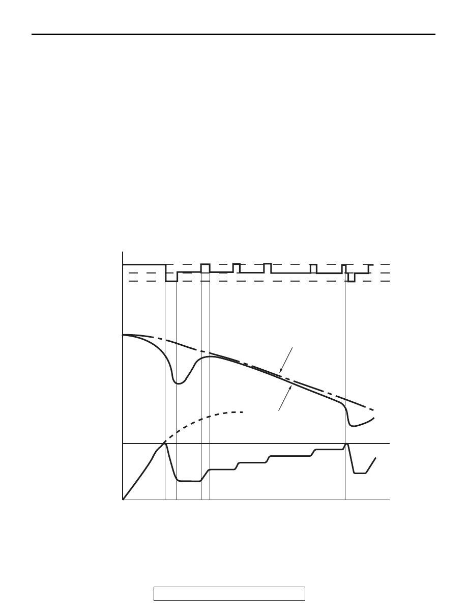
ABS CONTROL CYCLE
1. ASC-ECU calculates the speed and deceleration
of each wheel based on the signals from the
wheel speed sensors and G and yaw rate sensors
of four wheels, and estimates the vehicle speed of
at that time.
AC506830AB
a
b
c
d
A
B
C
D
e
Increase
Hold
Decrease
Wheel speed
Brake pressure
Actual vehicle speed
Estimated vehicle speed