Mitsubishi Evolution X. Manual - part 151
TRANSAXLE CONTROL
TSB Revision
TWIN CLUTCH-SPORTRONIC SHIFT TRANSMISSION (TC-SST)
22B-17
TRANSAXLE CONTROL
GENERAL INFORMATION
M2222000100383
In order to differentiate the TC-SST assembly shift
lever from A/T and CVT, a new exclusive shift lever
has been developed whose appearance is made
similar to that for M/T. It offers the following features.
• Sporty, straight type shift lever operation has
been adopted, and the operating power at each
shift position have been properly tuned, ensuring
the firm and smooth operation feel.
• The manual mode (6-speed) has been installed
to allow manual shifting according to the driver's
operation.
• ECU that is incorporated in the shift lever trans-
mits the lever position information and others to
TC-SST-ECU via CAN (main circuit) and LIN
(auxiliary circuit).
• For the parking lock mechanism, the transaxle
control cable is adopted.
• The electrical control-type shift lock (shift lever
cannot be shifted to the position other than P
position unless the brake pedal is depressed)
mechanism with the solenoid has been adopted
to facilitate the tuning work in assembly. The
cable type having an established past record is
adopted for the key interlock mechanism.
• Spherical shift knob is used to achieve the same
quality as that for M/T.
• As a mis-operation preventative mechanism
between P and R range, the pull ring has been
adopted.
• The main components have been made of resin
to reduce weight and number of components.
ERRONEOUS OPERATION PREVENTION MECHANISMS
M2222004000021
SHIFT LOCK MECHANISM
This is basically the same as with the electric shift
lock mechanism which is used for OUTLANDER.
KEY INTERLOCK MECHANISM
This is basically the same as with the cable-type key
interlock mechanism which is used for A/T vehicles.
AC705528
AC709661
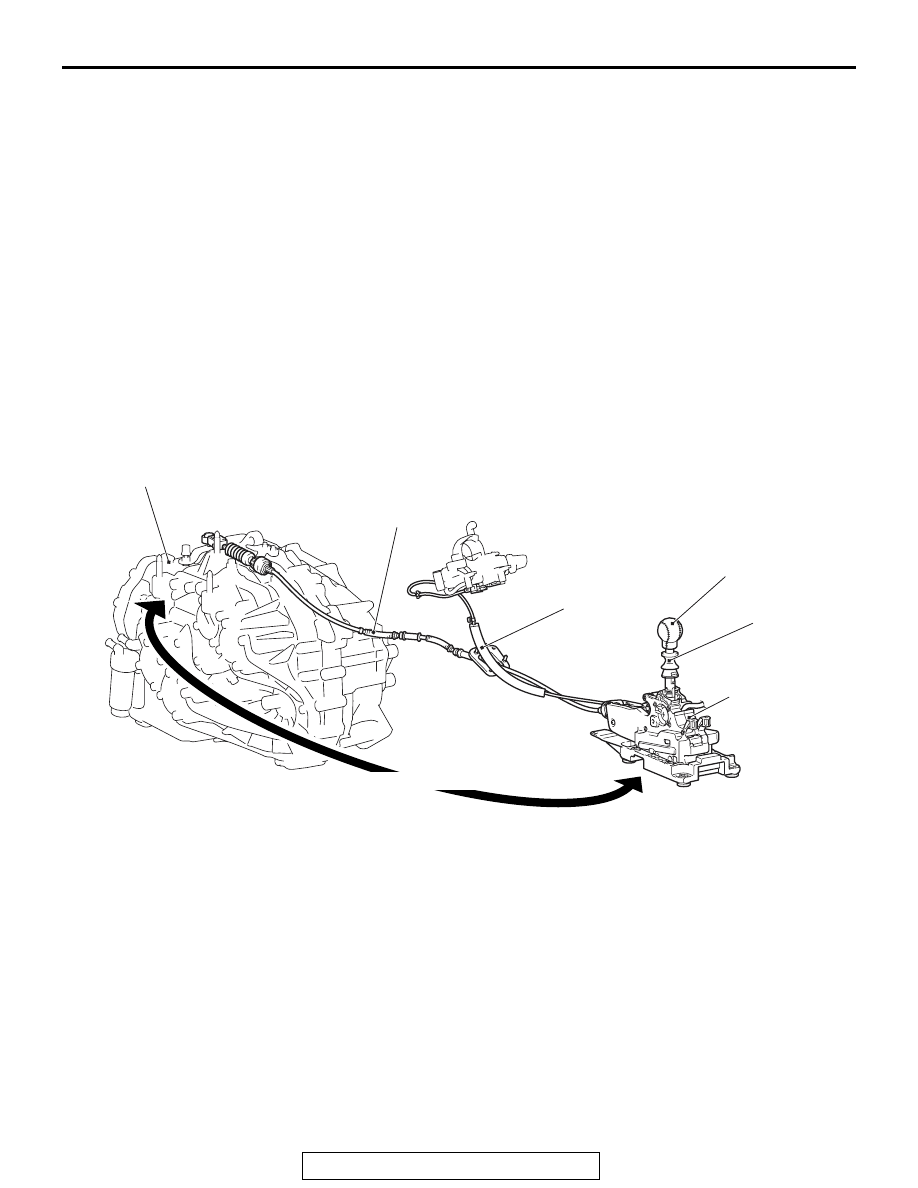
Shift knob
Shift lever assembly
(Incorporates shift lock
solenoid and ECU)
Transaxle assembly
Key interlock cable
Transaxle control
cable assembly
AB
CAN and LIN communication
Pull-ring