Mitsubishi Evolution X. Manual - part 126


  Index      Mitsubishi     Mitsubishi Evolution X - service repair manual 2008 year


Search            


Content   ..  124  125  126  127   ..


Mitsubishi Evolution X. Manual - part 126


FUEL INJECTION CONTROL

TSB Revision

MULTIPORT FUEL SYSTEM (MFI)

13A-33

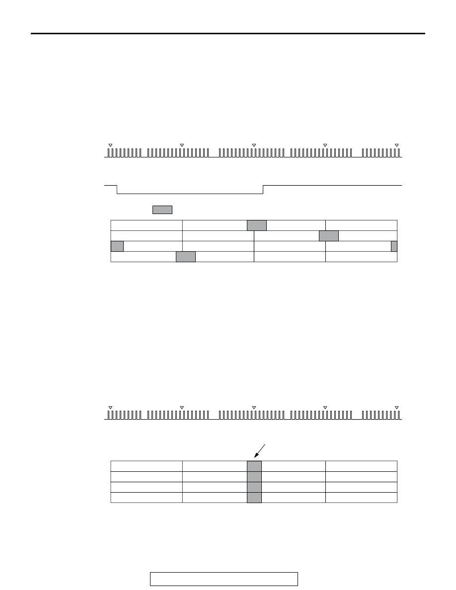
1. INJECTOR ACTUATION (FUEL INJECTION) 
TIMING

Injector drive time in case of multiport fuel injection (MFI) is 
controlled as follows according to driving conditions.

Fuel Injection During Cranking and Normal Operation

Fuel injection to each cylinder is done by driving the injector at 
optimum timing while it is in exhaust process based on the 
crankshaft position sensor signal. ECM compares the crank-
shaft position sensor output pulse signal and intake camshaft 
position sensor output pulse signal to identify the cylinder. 
Using this as a base, it performs sequential injection in the 
sequence of cylinders 1, 3, 4, 2.

Additional Fuel Injection During Acceleration

In addition to the synchronizing fuel injection with crankshaft 
position sensor signal during acceleration, the volume of fuel is 
injected according to the extent of the acceleration.

AK703691

<No. 2 TDC>

H

L

H

L

<No. 1 TDC>

<No. 3 TDC>

<No. 4 TDC>

<No. 2 TDC>

AC

Crankshaft
position
sensor
signal

Intake
camshaft
position
sensor
signal

Cylinder stroke

No. 1 cylinder

No. 2 cylinder

No. 3 cylinder

No. 4 cylinder

Combustion

Intake

Exhaust

Combustion

Exhaust

Compression

: Fuel injection

Intake

Exhaust

Compression

Combustion

Intake

Compression

Intake

Exhaust

Combustion

Compression

AK703786

<No. 2 TDC>

H

L

<No. 1 TDC>

<No. 3 TDC>

<No. 4 TDC>

<No. 2 TDC>

AC

Crankshaft
position
sensor
signal

Cylinder stroke

No. 1 cylinder

No. 2 cylinder

No. 3 cylinder

No. 4 cylinder

Combustion

Intake

Exhaust

Combustion

Exhaust

Increase injection for acceleration

Compression

Intake

Exhaust

Compression

Combustion

Intake

Compression

Intake

Exhaust

Combustion

Compression

FUEL INJECTION CONTROL

TSB Revision

MULTIPORT FUEL SYSTEM (MFI)

13A-34

2. Fuel injection volume (injector drive time) 

control

The figure shows the flow for injector drive time calculation. 

Basic drive time is decided based on the mass airflow sensor 

signal (intake air volume signal) and crankshaft position sensor 

signal (engine rotation signal). This basic drive time is compen-

sated according to signals from various sensors and optimum 

injector drive time (fuel injection volume) is calculated accord-

ing to driving conditions.

Fuel Injection Volume Control Block Diagram

AK702858AD

Manifold absolute
pressure sensor

Battery voltage
compensation

Battery voltage

Basic fuel
injection time
determination

Air-fuel ratio
compensation
(predetermined
compensation)

Injector

Crankshaft position
sensor

Heated oxygen sensor

Engine coolant
temperature sensor

Intake air temperature
sensor 1

Intake air temperature
sensor 2

Barometric pressure
sensor

Mass airflow sensor

Heated oxygen
sensor feedback
compensation

Engine coolant
temperature
compensation

Intake air
temperature
compensation

Acceleration-
deceleration
compensation

Barometric
pressure
compensation

Intake air
temperature
and pressure
in intake manifold
compensation

FUEL INJECTION CONTROL

TSB Revision

MULTIPORT FUEL SYSTEM (MFI)

13A-35

.

[Injector basic drive time]

Fuel injection is performed once per cycle for each cylinder. 
Basic drive time refers to fuel injection volume (injector drive 
time) to achieve theoretical air-fuel ratio for the intake air vol-
ume of 1 cycle of 1 cylinder.

Intake air volume of each cycle of 1 cylinder is calculated by 
ECM based on the mass airflow sensor signal and crankshaft 
position sensor signal. Also, during engine start, the map value 
prescribed by the engine coolant temperature sensor signal is 
used as basic drive time.

.

[Injector drive time compensation]

After calculating the injector basic drive time, the ECM makes 
the following compensations to control the optimum fuel injec-
tion volume according to driving conditions.

AK703134AD

Basic fuel
injection time

Intake air amount per cycle per cylinder

Theoretical air-fuel ratio

FUEL INJECTION CONTROL

TSB Revision

MULTIPORT FUEL SYSTEM (MFI)

13A-36

List of main compensations for fuel injection control

.

[Fuel limit control during deceleration]

ECM limits fuel when decelerating downhill to prevent exces-
sive rise of catalytic converter temperature and to improve fuel 
efficiency.

.

[Fuel-cut control when over-run]

When engine speed exceeds a prescribed limit (7,600 r/min), 
ECM cuts fuel supply to prevent overrunning and thus protect 
the engine. Also, if engine speed exceeds 4,000 r/min for 30 
seconds while vehicle is stationary (no load), it cuts fuel supply 
to protect the engine.

Compensations

Content

Heated oxygen sensor feedback compensation

The heated oxygen sensor signal is used for 
making the compensation to get air-fuel ratio with 
best cleaning efficiency of the 3-way catalytic 
converter. This compensation might not be made 
sometimes in order to improve drivability, 
depending on driving conditions. (Air-fuel ratio 
compensation is made.)

Air-fuel ratio compensation

Under driving conditions where heated oxygen 
sensor feedback compensation is not performed, 
compensation is made based on pre-set map 
values that vary according to engine speed and 
intake air volume.

Engine coolant temperature compensation

Compensation is made according to the engine 
coolant temperature. The lower the engine coolant 
temperature, the greater the fuel injection volume.

Acceleration/ Deceleration compensation

Compensation is made according to change in 
intake air volume. During acceleration, fuel injection 
volume is increased. Also, during deceleration, fuel 
injection volume is decreased.

Intake air temperature compensation

Compensation is made according to the intake air 
temperature. The lower the intake air temperature, 
the greater the fuel injection volume.

Barometric pressure compensation

Compensation is made according to the barometric 
pressure. The lower the barometric pressure, the 
smaller the fuel injection volume.

Battery voltage compensation

Compensation is made depending on battery 
voltage. The lower the battery voltage, the greater 
the injector drive signal time.

Intake air temperature and pressure in intake 
manifold compensation

Compensation is made according to the intake air 
temperature and pressure in the intake manifold.

Learning value for fuel compensation

Compensation amount is learned to compensate 
feedback of heated oxygen sensor. This allows 
system to compensate in accordance with engine 
characteristics.


Content   ..  124  125  126  127   ..