Mitsubishi Evolution X. Manual - part 113


  Index      Mitsubishi     Mitsubishi Evolution X - service repair manual 2008 year


Search            


Content   ..  111  112  113  114   ..


Mitsubishi Evolution X. Manual - part 113


SYSTEM OPERATION

TSB Revision

CONTROLLER AREA NETWORK (CAN)

54C-5

SYSTEM OPERATION

M2542000300272

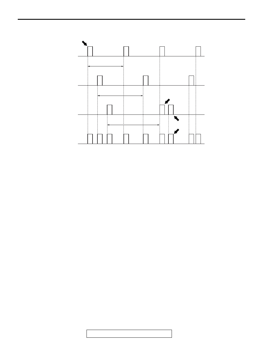
The CAN communication system is described below.

• Each ECU communicating with CAN periodically 

sends several sensors’ information on CAN bus 
as data frame (called periodical sending data). 
For further details, consult the data frame section.

• ECUs requiring data on CAN bus can receive 

data frames sent from each ECU simultaneously.

• The data sent from each ECU conducting CAN 

communication is transmitted at 10-10000 msec 
interval depending on necessity of data.
NOTE: In the figure above, the data frame A is 
transmitted in "a" intervals, while the data frames 
B and C are transmitted at intervals "b" and "c," 
respectively.

• A single ECU transmits multiple data frames.

• When data frames conflict with one another 

(when plural ECUs transmit signals simulta-
neously), data is prioritised for transmission by 
mediation, therefore, plural data frames are not 
sent simultaneously. For further details, consult 
the mediation section.

• Data is transmitted not by the conventional volt-

age-using method but by voltage potential differ-
ence. For further details, consult the section on 
CAN bus voltage transformation.

• Reliability of each ECU transmitting signals via 

CAN communication is secured by several error 
detection and recovery processes. For further 
details, consult the sections on error detection 
and system recovery.

• For major communication signals (transmitting 

signals) among ECUs.

.

MEDIATION

Because each ECU transmits data independently on 
the CAN bus, there are cases of data collision when 
multiple data frames that ECUs attempt to transmit 
simultaneously (if multiple ECUs transmit at nearly 
the same moment). At this moment, processing of 
the ECUs attempting transmission is performed in 
the following way.

1. Data frame with high priority is transmitted first 

according to ID codes memorized in data frames.

2. Transmission of low-priority data (data frames) is 

suspended by the issuing ECUs until the bus 
clears (when no transmission data exists on the 
CAN bus).
NOTE: If the suspended state continues for a 
specific time, new data (data frame content) is 
created and sent.

3. ECU containing suspended data frames trans-

mits the data when the bus becomes available.

NOTE: There is enough capacity on the CAN bus, 
which never prevents data frames from being sent.

.

AC206267

ECU-1

A

A

A

A

B

B

B

C

C

A

B

Interval "a"

Interval "b"

Interval "c"

C

C

C

B

B

A

A

A

ECU-1

ECU-2

CAN bus

Data frames

AC206267AD

Transmission 
suspended by 
mediation

Re-
transmission

SYSTEM OPERATION

TSB Revision

CONTROLLER AREA NETWORK (CAN)

54C-6

VOLTAGE TRANSFORMATION ON THE CAN-B BUS and CAN-C BUS

The voltage transformation (output signal) when the 
data frame is sent to the CAN-C bus line has a dis-
tinctive CAN-C profile. The transmitting ECU through 
the CAN_H and CAN_L bus lines sends 2.5 to 3.5 V 
signals to the CAN_H side and 2.5 to 1.5 V signals to 
the CAN_L side. The receiving ECU reads the data 
from the CAN_H and CAN_L potential difference. 
"Recessive" refers to the state where both CAN_H 
and CAN_L are under the 2.5 V state, and "Domi-
nant" refers to the state where CAN_H is under the 
3.5 V state and CAN_L is under the 1.5 V state. On 
the other hand, the voltage transformation (output 
signal) when the data frame is sent to the CAN-B bus 
line has a distinctive CAN-B profile. The transmitting 
ECU through the CAN_H and CAN_L bus lines 

sends 0 to 4 V signals to the CAN_H side, and 1 to 5 
V signals to the CAN_L side. "Recessive" is a state 
in which CAN_H is at 0 V and CAN_L is at 5 V, and 
"Dominant" is a state in which CAN_H is at 4 V and 
CAN_L is at 1 V. By transformation mainly to 2.5 V, 
even in cases when voltage is rendered 0 from faulty 
grounding or the like (causing a problem of an 
approximate 0.5 V increase on the communications 
line), communication can be continued uninter-
rupted. Employing dual communications lines 
improves reliability to prevent the presence of noise, 
compared to the conventional communication 
method.

.

AC507623

CAN_H

3.5 V

2.5 V

1.5 V

0

1

5 V

4 V

1 V

0 V

0

1

AB

CAN_L

<CAN-C>

<CAN-B>

VOLTAGE 
TRANSFORMATION 
IN CAN_L

STATE: 

LOGIC VALUE:

RECESSIVE

RECESSIVE

DOMINANT

VOLTAGE 
TRANSFORMATION 
IN CAN_H

RECESSIVE

RECESSIVE

DOMINANT

SYSTEM OPERATION

TSB Revision

CONTROLLER AREA NETWORK (CAN)

54C-7

DATA FRAMES

The data frame, which is sent from each ECU (or 
sensor) to the CAN bus line, consists of the fields 
below.

SOF (Start of Frame)

• Indicates the start of the frame

ID (Identifier) region

• Identifies the data content while specifying prior-

ity rank in case of mediation

Control region

• Specifies the frame type, data length, etc.

Data region

• Values used for data control, etc.

Cyclic Redundancy Check (CRC) region

• Region where to check for errors in sent data. 

The transmitting ECU calculates data regions by 
applying prescribed operations and stores the 
results. The receiving ECU detects erroneous 
communication by comparing the CRC region 
with the data region.

ACK (Acknowledge) region

• Region where to conform the reception of sent 

data

EOF (End of Frame)

• Indicates the end of the frame

.

ERROR DETECTION AND RECOVERY

CAN protocol secures its reliability of communication 
by providing several error detection function such as 
CRC shown in data frame, and the recovery function 
(recovery is performed by resending, from abnormal 
state such as transmission errors). If an error is 
detected but it is not resolved even after recovery, 
communication is stopped. This state is called "Bus 
Off."

AC504950

SOF

EOF

AB

ID 

REGION

CRC 

REGION

ACK 

REGION

CONTROL 
REGION

DATA REGION

DATA FRAMES

SELF-DIAGNOSIS

TSB Revision

CONTROLLER AREA NETWORK (CAN)

54C-8

SELF-DIAGNOSIS

M2542000400235

• CAN self-diagnosis is performed by each ECU 

connected to the CAN bus.

• diagnosis codes related to communication are 

named with the capital letter U, and are called 
"U-codes."

• A summary of the CAN self-diagnosis system is 

presented below. For further details on each 
diagnosis code stored by the ECUs.

.

TIME-OUT

Each ECU transmits data frames periodically. If the 
data frame is not received within the specified period, 
the intended receiving ECU transmits a diagnosis 
code indicating communication time-out for the ECU 
that failed to transmit.

.

BUS OFF

Related to a communication error that persists even 
after the transmitting ECU attempts recovery for a 
specified number of attempts or that persists for a 
specified period after recovery. Communication is 
stopped and this diagnostic code is issued.

CAN BUS DIAGNOSTICS

M2542000500254

As ECUs are connected via CAN bus (including scan 
tool), always diagnose CAN bus to confirm its nor-
mality when inspecting. Simply by performing scan 
tool screen operations, the following inspections can 
be performed automatically, and the result can be 
used to verify the CAN bus status.

• Confirmation of diagnosis code of ETACS-ECU

• Confirmation of communication of all ECUs


Content   ..  111  112  113  114   ..