Mitsubishi Evolution X. Manual - part 1120


  Index      Mitsubishi     Mitsubishi Evolution X - service repair manual 2008 year


Search            


Content   ..  1118  1119  1120  1121   ..


Mitsubishi Evolution X. Manual - part 1120


DIAGNOSIS

TSB Revision

CONTROLLER AREA NETWORK (CAN)

54C-115

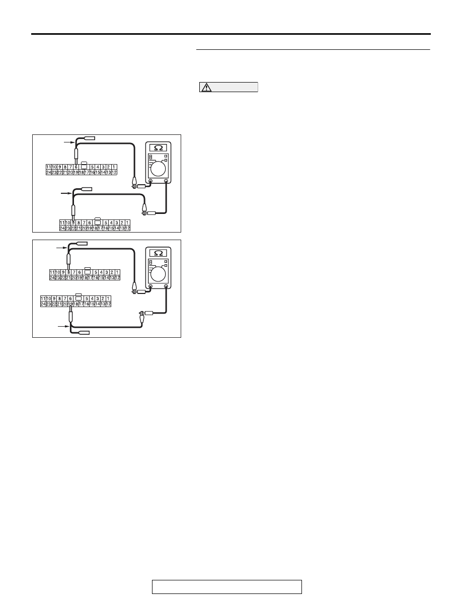
STEP 2. Check the wiring harness between joint connector 
(CAN2) C-104 and ETACS-ECU connector C-301 for open 
circuit.

CAUTION

Strictly observe the specified wiring harness repair proce-
dure. For details refer to 

P.54C-7

.

(1) Disconnect joint connector (CAN2) C-104 and ETACS-ECU 

connector C-301, and check the wiring harness.

(2) Check the wiring harness between joint connector (CAN2) 

C-104 (terminal 6) and ETACS-ECU connector C-301 
(terminal 9)

OK: Continuity exists (2 

 or less)

(3) Check the wiring harness between joint connector (CAN2) 

C-104 (terminal 19) and ETACS-ECU connector C-301 
(terminal 8)

OK: Continuity exists (2 

 or less)

Q: Is the wiring harness between joint connector (CAN2) 

C-104 and ETACS-ECU connector C-301 in good 
condition?
YES : 
Go to Step 3.
NO :  Repair the wiring harness between joint connector 

(CAN2) C-104 and ETACS-ECU connector C-301.

AC709707BP

Harness side: C-104

TEST 
HARNESS

Harness side: C-301

TEST 
HARNESS

AC709707BQ

Harness side: C-104

TEST 
HARNESS

Harness side: C-301

TEST 
HARNESS

DIAGNOSIS

TSB Revision

CONTROLLER AREA NETWORK (CAN)

54C-116

STEP 3. Using scan tool MB991958, diagnose the CAN bus 
line.

CAUTION

To prevent damage to scan tool MB991958, always turn the 
ignition switch to the "LOCK" (OFF) position before con-
necting or disconnecting scan tool MB991958.
(1) Connect scan tool MB991958 to the data link connector.
(2) Turn the ignition switch to the "ON" position.

(3) Diagnose CAN bus lines, and check if the scan tool screen 

is as shown in the illustration.

Q: Does the scan tool screen correspond to the 

illustration?
YES : 
The trouble can be an intermittent malfunction (Refer 

to GROUP 00, How to use 
Troubleshooting/inspection Service Points 

− How to 

Cope with Intermittent Malfunction 

P.00-15

).

NO :  Replace the ETACS-ECU.

AC608435

Data link connector

MB991827

MB991824

MB991910

AB

AC709542 AB

: Red section on screen

M.U.T.

J/C (3)

SAS

J/C (2)

KOS/WCM

SRS

A/C

AUDIO

MMCS

Sat Radio

HFM

OCM

METER

ASC

ENGINE

J/C (1)

ETACS

<M/T>

S-AWC

AC709543 AB

: Red section on screen

M.U.T.

J/C (3)

SAS

J/C (2)

KOS/WCM

SRS

A/C

AUDIO

MMCS

Sat Radio

HFM

OCM

METER

ASC

LEVER

ENGINE

J/C (1)

ETACS

<TC-SST>

S-AWC

TC-SST

J/C (4)

DIAGNOSIS

TSB Revision

CONTROLLER AREA NETWORK (CAN)

54C-117

DIAGNOSTIC ITEM 13: Diagnose the lines between joint connector (CAN2) and joint connector 
(CAN3).

CAUTION

When servicing a CAN bus line, ground yourself by touching a metal object such as an unpainted 
water pipe. If you fail to do so, a component connected to the CAN bus line may be damaged.

CAN-C Communication Circuit <M/T>

ETACS-ECU

INTERFACE
CIRCUIT

CAN DRIVE
CIRCUIT

JOINT CONNECTOR
(CAN2)

JOINT CONNECTOR
(CAN3)

ASC-ECU

STEERING
WHEEL SENSOR

S-AWC-ECU

ENGINE
CONTROL
MODULE

DIAGNOSIS

TSB Revision

CONTROLLER AREA NETWORK (CAN)

54C-118

TRANSAXLE 
ASSEMBLY

ENGINE 
CONTROL 
MODULE

CAN-C Communication Circuit <TC-SST>

ETACS-ECU

INTERFACE
CIRCUIT

CAN DRIVE
CIRCUIT

JOINT CONNECTOR
(CAN2)

JOINT CONNECTOR
(CAN3)

JOINT CONNECTOR
(CAN4)

SHIFT LEVER

ASC-ECU

STEERING
WHEEL SENSOR

S-AWC-ECU

NOTE

: THE TERMINAL NUMBERS DESCRIBED 

IN THE CIRCUIT DIAGRAM AGREE WITH 
THE NUMBERS MAKED ON THE 
TRANSAXLE ASSEMBLY CONNECTOR AND 
HARNESS SIDE CONNECTOR.


Content   ..  1118  1119  1120  1121   ..