Mitsubishi Evolution X. Manual - part 1108


  Index      Mitsubishi     Mitsubishi Evolution X - service repair manual 2008 year


Search            


Content   ..  1106  1107  1108  1109   ..


Mitsubishi Evolution X. Manual - part 1108


DIAGNOSIS

TSB Revision

CONTROLLER AREA NETWORK (CAN)

54C-67

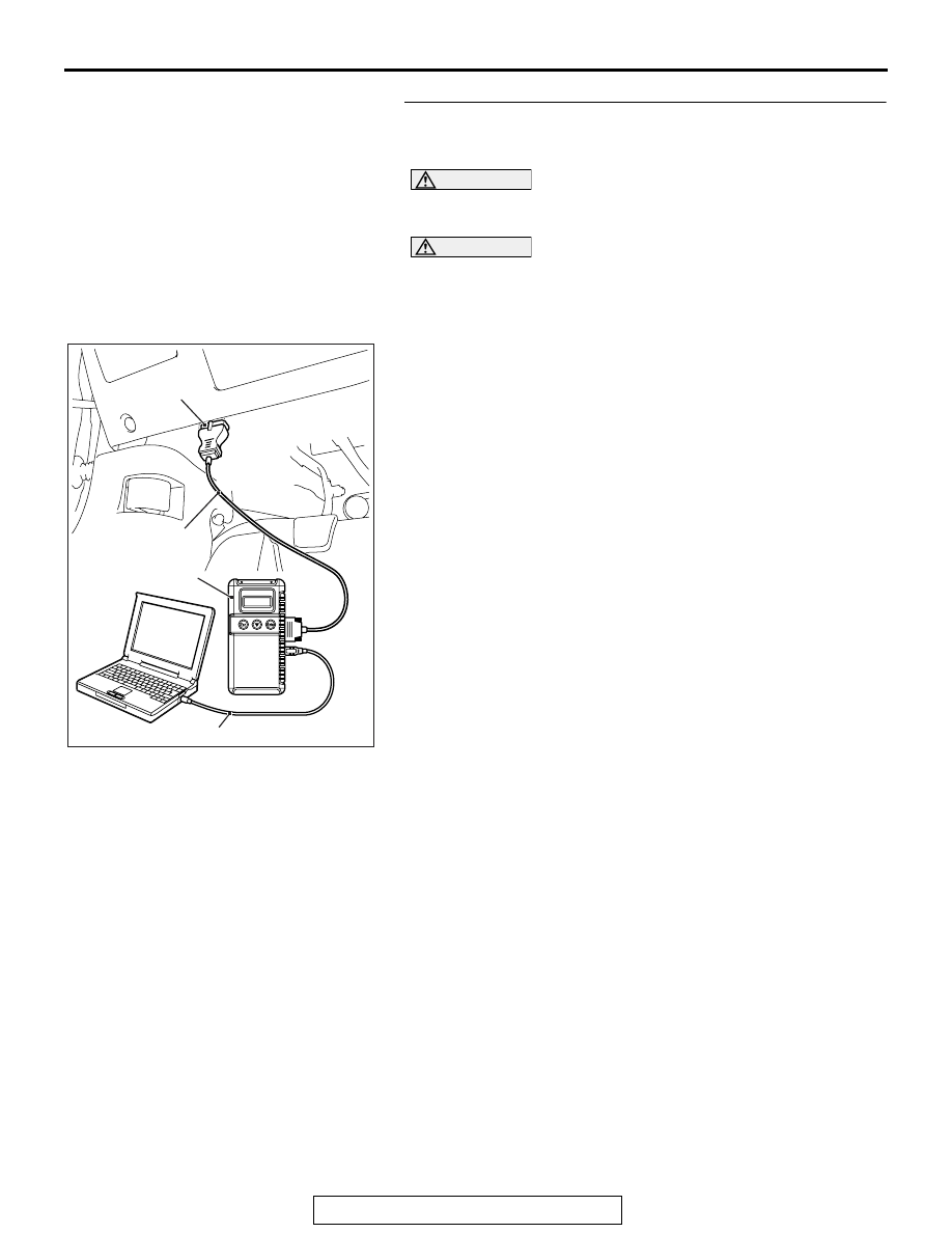
STEP 15. Using scan tool MB991958, diagnose the CAN 
bus line. (checking the shift lever for internal short to 
ground)

CAUTION

Strictly observe the specified wiring harness repair proce-
dure. For details refer to 

P.54C-7

.

CAUTION

To prevent damage to scan tool MB991958, always turn the 
ignition switch to the "LOCK" (OFF) position before con-
necting or disconnecting scan tool MB991958.
(1) Disconnect shift lever connector C-27.
(2) Connect scan tool MB991958 to the data link connector.
(3) Turn the ignition switch to the "ON" position.

AC608435

Data link connector

MB991827

MB991824

MB991910

AB

DIAGNOSIS

TSB Revision

CONTROLLER AREA NETWORK (CAN)

54C-68

(4) Diagnose CAN bus lines, and check if the scan tool 

MB991958 screen is as shown in the figure.

OK: The display of the scan tool MB991958 is as 
shown in the figure.

Q: Does scan tool MB991958 screen correspond to the 

illustration?
YES : 
Repair the wiring harness between shift lever 

connector C-27 and joint connector (CAN3) C-127.

NO :  Check shift lever connector C-27, and repair if 

necessary. If the shift lever connector is in good 
condition, replace the shift lever.

STEP 16. Using scan tool MB991958, diagnose the CAN 
bus line. (checking the TC-SST-ECU for internal short to 
ground)

CAUTION

Strictly observe the specified wiring harness repair proce-
dure. For details refer to 

P.54C-7

.

CAUTION

To prevent damage to scan tool MB991958, always turn the 
ignition switch to the "LOCK" (OFF) position before con-
necting or disconnecting scan tool MB991958.
(1) Disconnect transaxle assembly connector B-107.

AC709542 AC

: Red section on screen

M.U.T.

J/C (3)

J/C (2)

KOS/WCM

SRS

A/C

AUDIO

MMCS

Sat Radio

HFM

OCM

METER

ASC

ENGINE

J/C (1)

ETACS

<M/T>

SAS

S-AWC

AC709543 AC

: Red section on screen

M.U.T.

J/C (3)

J/C (2)

KOS/WCM

SRS

A/C

AUDIO

MMCS

Sat Radio

HFM

OCM

METER

ASC

LEVER

J/C (1)

ETACS

<TC-SST>

SAS

S-AWC

J/C (4)

TC-SST

ENGINE

DIAGNOSIS

TSB Revision

CONTROLLER AREA NETWORK (CAN)

54C-69

(2) Connect scan tool MB991958 to the data link connector.
(3) Turn the ignition switch to the "ON" position.

(4) Diagnose CAN bus lines, and check if the scan tool 

MB991958 screen is as shown in the figure.

OK: The display of the scan tool MB991958 is as 
shown in the figure.

Q: Does scan tool MB991958 screen correspond to the 

illustration?
YES : 
Repair the wiring harness between transaxle 

assembly connector B-107 and joint connector 
(CAN4) A-14.

NO :  Check transaxle assembly connector B-107, and 

repair if necessary. If the transaxle assembly 
connector is in good condition, replace the transaxle 
assembly.

AC608435

Data link connector

MB991827

MB991824

MB991910

AB

AC709542 AC

: Red section on screen

M.U.T.

J/C (3)

J/C (2)

KOS/WCM

SRS

A/C

AUDIO

MMCS

Sat Radio

HFM

OCM

METER

ASC

ENGINE

J/C (1)

ETACS

<M/T>

SAS

S-AWC

AC709543 AC

: Red section on screen

M.U.T.

J/C (3)

J/C (2)

KOS/WCM

SRS

A/C

AUDIO

MMCS

Sat Radio

HFM

OCM

METER

ASC

LEVER

J/C (1)

ETACS

<TC-SST>

SAS

S-AWC

J/C (4)

TC-SST

ENGINE

DIAGNOSIS

TSB Revision

CONTROLLER AREA NETWORK (CAN)

54C-70

DIAGNOSTIC ITEM 5: Diagnose shorts in the power supply to CAN-C bus line.

CAN-C Communication Circuit <M/T>

ETACS-ECU

INTERFACE
CIRCUIT

CAN DRIVE
CIRCUIT

JOINT CONNECTOR
(CAN2)

JOINT CONNECTOR
(CAN3)

ASC-ECU

STEERING
WHEEL SENSOR

S-AWC-ECU

ENGINE
CONTROL
MODULE


Content   ..  1106  1107  1108  1109   ..