Mitsubishi Evolution X. Manual - part 1050


  Index      Mitsubishi     Mitsubishi Evolution X - service repair manual 2008 year


Search            


Content   ..  1048  1049  1050  1051   ..


Mitsubishi Evolution X. Manual - part 1050


SATELLITE RADIO TUNER

TSB Revision

CHASSIS ELECTRICAL

54A-561

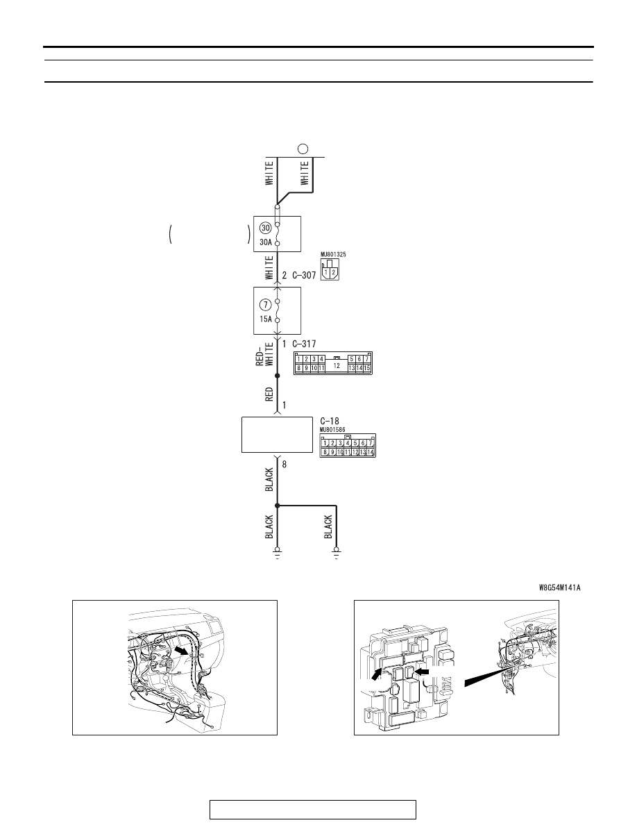
Inspection Procedure 2: Check the satellite radio tuner power supply circuit.

.

Satellite Radio Tuner Supply Circuit

FUSIBLE
LINK

36

SATELLITE
RADIO
TUNER

RELAY BOX
 ENGINE 
 COMPARTMENT

AC708951BX

Connector: C-18

AC708972BA

Connectors: C-307, C-317

ETACS-ECU

C-307 (B)

C-317

SATELLITE RADIO TUNER

TSB Revision

CHASSIS ELECTRICAL

54A-562

TECHNICAL DESCRIPTION (COMMENT)

If the satellite radio tuner functions do not work at all, 
the satellite radio tuner power supply system, ground 
system, or satellite radio tuner may have a problem.

.

TROUBLESHOOTING HINTS

• The wiring harness or connectors may have 

loose, corroded, or damaged terminals, or termi-
nals pushed back in the connector

• The satellite radio tuner may be defective

DIAGNOSIS

Required Special Tools:

• MB991223: Harness Set

• MB992006: Extra Fine Probe

STEP 1. Check satellite radio tuner connectors C-18 for 
loose, corroded or damaged terminals, or terminals 
pushed back in the connector.
Q: Is satellite radio tuner connectors C-18 in good 

condition?
YES : 
Go to Step 2.
NO :  Repair or replace the damaged component(s). Refer 

to GROUP 00E, Harness Connector Inspection 

P.00E-2

.

STEP 2. Check the ground circuit to the satellite radio 
tuner. Measure the resistance at satellite radio tuner 
connectors C-18.
(1) Disconnect satellite radio tuner connector C-18 and 

measure the resistance available at the wiring harness side 
of the connector.

(2) Measure the resistance value between satellite radio tuner 

connector C-18 terminal 8 and ground.

• The resistance should be 2 ohms or less.

Q: Is the measured resistance 2 ohms or less?

YES : Go to Step 4.
NO :  Go to Step 3.

STEP 3. Check the wiring harness between satellite radio 
tuner connector C-18 (terminal 8) and ground.
Q: Is the wiring harness between satellite radio tuner 

connector C-18 (terminal 8) and ground in good 
condition?
YES : 
No action is necessary and testing is complete.
NO :  The wiring harness may be damaged or the 

connector(s) may have loose, corroded or damaged 
terminals, or terminals pushed back in the connector. 
Repair the wiring harness as necessary.

AC709322 BL

Harness side: C-18

SATELLITE RADIO TUNER

TSB Revision

CHASSIS ELECTRICAL

54A-563

STEP 4. Check the power supply circuit to the satellite 
radio tuner. Measure the voltage at satellite radio tuner 
connector C-18.
(1) Disconnect the connector, and measure at the wiring 

harness-side connector.

(2) Measure the voltage between terminal 1 and ground.

OK: Battery voltage

Q: Is the measured voltage battery voltage?

YES : Go to Step 6.
NO :  Go to Step 5.

STEP 5. Check the wiring harness between satellite radio 
tuner connector C-18 (terminal 1) and fusible link (36).
NOTE: Also check ETACS-ECU connectors C-307 and C-317 
for loose, corroded, or damaged terminals, or terminals pushed 
back in the connector. If ETACS-ECU connector C-307 or 
C-317 is damaged, repair or replace the connector as 
described in GROUP 00E, Harness Connector Inspection 

P.00E-2

.

Q: Is the wiring harness between satellite radio tuner 

connector C-18 (terminal 1) and fusible link (36) in good 
condition?
YES : 
No action is necessary and testing is complete.
NO :  The wiring harness may be damaged or the 

connector(s) may have loose, corroded or damaged 
terminals, or terminals pushed back in the connector. 
Repair the wiring harness as necessary. The system 
should communicate with the satellite radio tuner 
normally.

STEP 6. Retest the system
Check if the satellite radio tuner works normally.
Q: Is the check result normal?

YES : The trouble can be an intermittent malfunction (Refer 

to GROUP 00, How to use 
Troubleshooting/inspection Service Points 

− How to 

Cope with Intermittent Malfunction 

P.00-15

).

NO :  Replace the satellite radio tuner.

AC709325 AV

Harness side: C-18

SATELLITE RADIO TUNER

TSB Revision

CHASSIS ELECTRICAL

54A-564

Inspection Procedure 3: The error code "ANTENNA ERROR" is displayed on the display.

.

TECHNICAL DESCRIPTION (COMMENT)

When there is a failure in the antenna base, antenna 
rod, or there is an open circuit or improper connec-
tion in the antenna feeder, and the satellite radio 
tuner cannot receive normal voltage value or current 
value, the error code "ANTENNA ERROR" is dis-
played on the display.

.

TROUBLESHOOTING HINTS

• Malfunction of the antenna rod.

• Malfunction of the antenna base.

• Malfunction of the antenna feeder cable.

• Malfunction of the satellite radio tuner.

.

DIAGNOSIS 

STEP 1. Check if the antenna base or antenna rod are 
damaged.
Q: Are the antenna base or antenna rod damaged?

YES : Replace the antenna base or antenna rod. 
NO :  Go to Step 2.

STEP 2. Check the connection between the antenna base 
and the antenna feeder.
Q: Is the connection between the antenna base and the 

antenna feeder normal?
YES : 
Go to Step 3.
NO :  Repair the connection.

STEP 3. Check if the antenna feeder is damaged.
Q: Is the antenna feeder damaged or bent?

YES : Repair or replace the antenna feeder.
NO :  Go to Step 4.

STEP 4. Check the connection between the antenna feeder 
cable and the satellite radio tuner.
Q: Is the connection between the antenna feeder and the 

satellite radio tuner normal?
YES : 
Go to Step 5.
NO :  Repair the connection.

STEP 5. Temporarily replace the antenna base, and check 
if "ANTENNA ERROR" is displayed on the display.
Q: Is "ANTENNA ERROR" displayed on the display?

YES : Replace the satellite radio tuner.
NO :  Replace the antenna base.


Content   ..  1048  1049  1050  1051   ..