Mitsubishi Evolution X. Manual - part 1024


  Index      Mitsubishi     Mitsubishi Evolution X - service repair manual 2008 year


Search            


Content   ..  1022  1023  1024  1025   ..


Mitsubishi Evolution X. Manual - part 1024


HANDS-FREE CELLULAR PHONE SYSTEM

TSB Revision

CHASSIS ELECTRICAL

54A-457

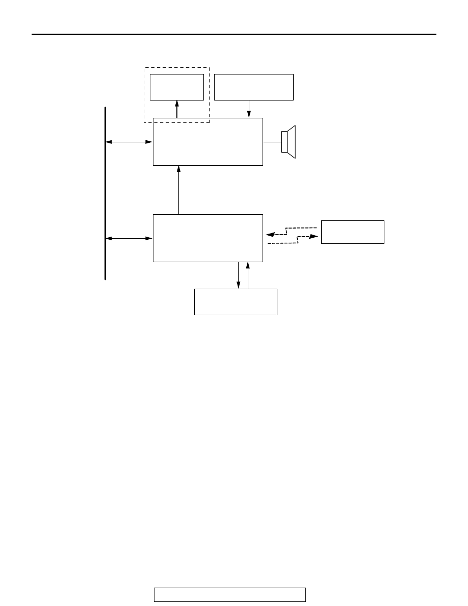
System block diagram

AC613221

Speaker

Audio display

*

1

Steering voice-control 
switch


Cellular phone

*1: Vehicles without MMCS

*2: Vehicles with MMCS

BluetoothTM

CAN bus line

CAN

CAN

Phone voice

Voice

Microphone power

Microphone unit 
(built in front dome light)

Hands-free module

AH

Radio and CD player*

1

or
Multivision display*

2

HANDS-FREE CELLULAR PHONE SYSTEM

TSB Revision

CHASSIS ELECTRICAL

54A-458

SPECIAL TOOLS

M1544403500038

Tool

Tool number and 
name

Supersession

Application

MB991958

a. MB991824
b. MB991827
c. MB991910
d. MB991911
e. MB991914
f. MB991825
g. MB991826

M.U.T.-III 
sub-assembly

a. Vehicle 

communication 
interface (V.C.I.)

b. M.U.T.-III USB 

cable

c. M.U.T.-III main 

harness A 
(Vehicles with 
CAN 
communication 
system)

d. M.U.T.-III main 

harness B 
(Vehicles without 
CAN 
communication 
system)

e. M.U.T.-III main 

harness C (for 
Daimler Chrysler 
models only)

f. M.U.T.-III 

measurement 
adapter

g. M.U.T.-III trigger 

harness

MB991824-KIT
NOTE: G: MB991826 
M.U.T.-III Trigger 
Harness is not 
necessary when 
pushing V.C.I. ENTER 
key.

CAUTION

M.U.T.-III main harness A 
(MB991910) should be used. 
M.U.T.-III main harness B and C 
should not be used for this 
vehicle.
CAN bus diagnostics or data list 
check.

MB991910

MB991826

MB991958

MB991911

MB991914

MB991824

MB991827

MB991825

DO NOT USE

a

b

c

d

e

f

g

DO NOT USE

HANDS-FREE CELLULAR PHONE SYSTEM

TSB Revision

CHASSIS ELECTRICAL

54A-459

DIAGNOSIS

STANDARD FLOW OF DIAGNOSTIC 
TROUBLESHOOTING

M1540203800011

Refer to GROUP 00 

− Contents of troubleshootin

P.00-7

.

DIAGNOSIS FUNCTION

M1544403100041

HOW TO CONNECT THE SCAN TOOL (M.U.T.-III)

Required Special Tools:

• MB991958: Scan Tool (M.U.T.-III Sub Assembly)

• MB991824: Vehicles Communication Interface (V.C.I.)

• MB991827: M.U.T.-III USB Cable

• MB991910: M.U.T.-III Main Harness A (Vehicles with 

CAN communication system)

MB991223

a. MB991219
b. MB991220
c. MB991221
d. MB991222

Harness set

a. Check harness
b. LED harness
c. LED harness 

adapter

d. Probe

General service tool 
(jumper)

Continuity check and voltage 
measurement at harness wire or 
connector

a. For checking connector pin 

contact pressure

b. For checking power supply 

circuit

c. For checking power supply 

circuit

d. For connecting a locally 

sourced tester

MB992006
Extra fine probe

Continuity check and voltage 
measurement at harness wire or 
connector

Tool

Tool number and 
name

Supersession

Application

MB991223

a

d

c

b

DO NOT USE

BA

MB992006

HANDS-FREE CELLULAR PHONE SYSTEM

TSB Revision

CHASSIS ELECTRICAL

54A-460

CAUTION

To prevent damage to scan tool MB991958, always turn the 
ignition switch to the "LOCK" (OFF) position before con-
necting or disconnecting scan tool MB991958.
1. Ensure that the ignition switch is at the "LOCK" (OFF) 

position.

2. Start up the personal computer.
3. Connect special tool MB991827 to special tool MB991824 

and the personal computer.

4. Connect special tool MB991910 to special tool MB991824.
5. Connect special tool MB991910 to the data link connector.
6. Turn the power switch of special tool MB991824 to the "ON" 

position.
NOTE: When special tool MB991824 is energized, special 
tool MB991824 indicator light will be illuminated in a green 
color.

7. Start the M.U.T.-III system on the personal computer.
NOTE: Disconnecting scan tool MB991958 is the reverse of the 
connecting sequence, making sure that the ignition switch is at 
the "LOCK" (OFF) position.

HOW TO READ AND ERASE DIAGNOSTIC 
TROUBLE CODES

Required Special Tools:

• MB991958: Scan Tool (M.U.T.-III Sub Assembly)

• MB991824: Vehicles Communication Interface (V.C.I.)

• MB991827: M.U.T.-III USB Cable

• MB991910: M.U.T.-III Main Harness A (Vehicles with 

CAN communication system)

NOTE: If the battery voltage is low, diagnostic trouble codes will 
not be set. Check the battery if scan tool MB991958 does not 
display.
1. Connect scan tool MB991958 to the data link connector.
2. Turn the ignition switch to the "ON" position.
3. Select "System select" from the start-up screen.
4. Select "From 2006 MY" of "Model Year." When the "Vehicle 

Information" is displayed, check the contents.

5. Select "Meter" from "System List," and press the "OK" 

button.
NOTE: When the "Loading Option Setup" list is displayed, 
check the applicable item.

6. Select "Diagnostic Trouble Code."
7. If a DTC is set, it is shown.
8. Choose "Erase DTCs" to erase the DTC.

AC608435

Data link connector

MB991827

MB991824

MB991910

AB


Content   ..  1022  1023  1024  1025   ..