Mitsubishi Evolution X. Manual - part 1005


  Index      Mitsubishi     Mitsubishi Evolution X - service repair manual 2008 year


Search            


Content   ..  1003  1004  1005  1006   ..


Mitsubishi Evolution X. Manual - part 1005


MMCS

TSB Revision

CHASSIS ELECTRICAL

54A-381

EACH LOG INFORMATION: FACTOR CODE TABLE

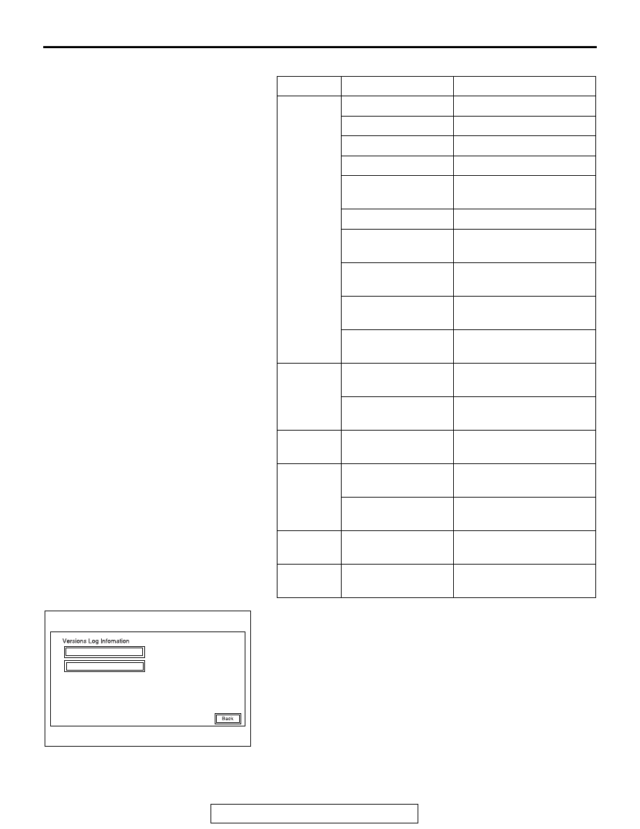
1. Select "Time Adjustment Log" on the "Versions Log Infor-

mation" screen.

Item

Factor number

Produced log

Drive

20

Log concerning focus

21

Log concerning disk type

22

Log concerning disc

25

Log concerning SEEK

26

Log concerning servo 
start-up

27

Log concerning power-On

28

Log concerning loading / 
eject operation

29

Log concerning pick-up 
operation

30

Log concerning state of 
mechanism

52

Log concerning TOC 
reading

HDD

1

Log concerning high 
temperature

2

Log concerning low 
temperature

Monitor

1

Log concerning high 
temperature

AMP

0

Log concerning 
connection

15

Log concerning 
communication

SP

*1

1,2,4,8

Log concerning number of 
speakers unexpected

CAR

*2

0 -12,     128 -131, 
133,160, 192,255

Log concerning vehicle 
model unexpected

AC611719

Service Data Log

Time Adjustment Log

AB

MMCS

TSB Revision

CHASSIS ELECTRICAL

54A-382

2. The time adjustment logs are displayed.

As for Factor, the following two types are displayed.
CT: Automatic adjustment
MAN: Manual adjustment

DIAGNOSIS FUNCTION

M1546001600231

HOW TO CONNECT THE SCAN TOOL (M.U.T.-III)

Required Special Tools:

• MB991958: Scan Tool (M.U.T.-III Sub Assembly)

• MB991824: Vehicles Communication Interface (V.C.I.)

• MB991827: M.U.T.-III USB Cable

• MB991910: M.U.T.-III Main Harness A (Vehicles with 

CAN communication system)

CAUTION

To prevent damage to scan tool MB991958, always turn the 
ignition switch to the "LOCK" (OFF) position before con-
necting or disconnecting scan tool MB991958.
1. Ensure that the ignition switch is at the "LOCK" (OFF) 

position.

2. Start up the personal computer.
3. Connect special tool MB991827 to special tool MB991824 

and the personal computer.

4. Connect special tool MB991910 to special tool MB991824.
5. Connect special tool MB991910 to the data link connector.
6. Turn the power switch of special tool MB991824 to the "ON" 

position.
NOTE: When special tool MB991824 is energized, special 
tool MB991824 indicator light will be illuminated in a green 
color.

7. Start the scan tool system on the personal computer.
NOTE: Disconnecting scan tool MB991958 is the reverse of the 
connecting sequence, making sure that the ignition switch is at 
the "LOCK" (OFF) position.

AC611720

Time Adjustment Information

After

Factor

Before

CT

CT

CT

CT

CT

CT

AB

AC608435

Data link connector

MB991827

MB991824

MB991910

AB

MMCS

TSB Revision

CHASSIS ELECTRICAL

54A-383

HOW TO READ AND ERASE DIAGNOSTIC 
TROUBLE CODES

Required Special Tools:

• MB991958: Scan Tool (M.U.T.-III Sub Assembly)

• MB991824: Vehicles Communication Interface (V.C.I.)

• MB991827: M.U.T.-III USB Cable

• MB991910: M.U.T.-III Main Harness A (Vehicles with 

CAN communication system)

NOTE: If the battery voltage is low, diagnostic trouble codes will 
not be set. Check the battery if scan tool MB991958 does not 
display.
1. Connect scan tool MB991958 to the data link connector.
2. Turn the ignition switch to the "ON" position.
3. Select "System select" from the start-up screen.
4. Select "From 2006 MY" of "Model Year." When the "Vehicle 

Information" is displayed, check the contents.

5. Select "Meter" from "System List," and press the "OK" 

button.
NOTE: When the "Loading Option Setup" list is displayed, 
check the applicable item.

6. Select "Diagnostic Trouble Code."
7. If a DTC is set, it is shown.
8. Choose "Erase DTCs" to erase the DTC.

HOW TO DIAGNOSE THE CAN BUS LINES

Required Special Tools:

• MB991958: Scan Tool (M.U.T.-III Sub Assembly)

• MB991824: Vehicles Communication Interface (V.C.I.)

• MB991827: M.U.T.-III USB Cable

• MB991910: M.U.T.-III Main Harness A (Vehicles with 

CAN communication system)

1. Connect scan tool MB991958 to the data link connector.
2. Turn the ignition switch to the "ON" position.
3. Select "CAN bus diagnosis" from the start-up screen.
4. When the vehicle information is displayed, confirm that it 

matches the vehicle being diagnosed.

• If they match, go to Step 8.

• If not, go to Step 5.

5. Select the "view vehicle information" button.
6. Enter the vehicle information and select the "OK" button.
7. When the vehicle information is displayed, confirm again 

that it matches the vehicle being diagnosed.

• If they match, go to Step 8.

• If not, go to Step 5.

8. Select the "OK" button.
9. When the optional equipment screen is displayed, choose 

the one which the vehicle is fitted with, and then select the 
"OK" button.

MMCS

TSB Revision

CHASSIS ELECTRICAL

54A-384

CHECK OF FREEZE FRAME DATA

The freeze frame data can be checked by using scan 
tool MB991958.

.

When detecting fault and storing the diagnostic trou-
ble code, the ECU connected to CAN bus line 
obtains the data before the determination of the diag-
nostic trouble code and the data when the diagnostic 
trouble code is determined, and then stores the ECU 
status of that time. By analyzing each data from scan 
tool MB991958, the troubleshooting can be per-
formed more efficiently. The displayed items are as 
the table below.

Display item list

DIAGNOSTIC TROUBLE CODE CHART

M1546001700197

CAUTION

On troubleshooting, if the ignition switch is 
turned ON while disconnecting connector(s), 
diagnostic trouble code(s) associated with other 
system may be set. On completion, confirm all 
systems for diagnostic trouble code(s). If diag-
nostic trouble code(s) are set, erase them all.

Item No.

Item name

Data item

Unit

1

Odometer

Total driving distance after the diagnostic trouble 
code is generated

km

2

Ignition cycle

Number of times the ignition switch is turned "ON" or 
"LOCK (OFF)" after the past failure transition

Number of 
counts is 
displayed.

4

Accumulated minute Cumulative time for current malfunction of 

diagnostic trouble code

min

DTC No. Description

Reference page

B2226

AND error

P.54A-385

B2240

Communication error with CAN Box

P.54A-387

B2477

VIN not programmed

P.54A-390

U0019

Bus off (CAN-B)

P.54A-391

U0141

ETACS CAN timeout

P.54A-392

U0151

SRS-ABG CAN timeout

P.54A-394

U0154

OCM CAN timeout

P.54A-396

U0155

Meter CAN timeout

P.54A-397

U0164

A/C CAN timeout

P.54A-399

U0168

WCM CAN timeout

P.54A-400

U0195

Satellite radio CAN timeout

P.54A-402

U0197

Hands free module CAN timeout

P.54A-403

U1415

Coding not completed/Data fail

P.54A-405

U1417

Implausible coding data

P.54A-406


Content   ..  1003  1004  1005  1006   ..