Mitsubishi Evolution X. Manual - part 3
WELDING
TSB Revision
BASE OF BODY REPAIR
9-9
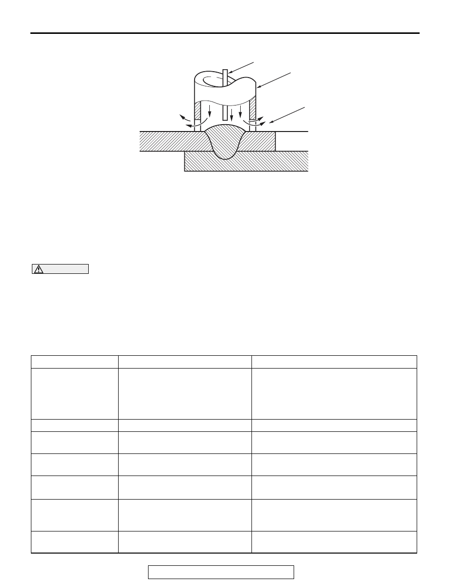
MIG SPOT WELDING
This welding method is used in areas where regular
spot welding cannot be done. The two panels are
stacked together, the tip of the torch (one designed
for use in MIG spot welding) is positioned on one
side, an arc is generated for a short time, and a par-
tial melting is done to obtain a spot weld.
.
Procedure
CAUTION
• Make sure that the area to be welded is per-
fectly clean; remove oxidation film, scales,
rust, dirt, etc.
• The two panels to be welded must be in per-
fect contact with each other.
• The number and pitch of the weld points
should be approximately the same as for the
factory welds.
1. Position the tip of the nozzle at a right angle to the
surface to be welded.
2. Being sure that the two prongs are not leaning to
either side, set them in direct contact with the
panel to the welded.
3. Welding will begin when the torch trigger is
squeezed, and will stop automatically when the
weld is complete.
.
FEATURES OF MIG SPOT WELDING
In comparison to resistance spot welding, MIG spot
welding has the following advantages and disadvan-
tages.
AB200036
Gas cup
Gas outlet
Wire
AE
Item
Mig spot welding
Electric resistance spot welding
Working
characteristics
• Light weight
• Welding possible at various
positions (no limit upon welding
positions)
• Although the torch with separate
transformer is lightweight, the torch
combined with transformer type is heavy.
• The arm must be exchanged to conform
to the weld location.
Weld time/point
Slow (0.5 second or more)
Fast (0.5 second or less)
Treatment after
welding
Necessary (grinding by grinder,
etc.)
Unnecessary
Power
High voltage, low current
(15
− 30 V, 50 − 200 A)
Low voltage, high current
(2
− 4 V, 4 − 10 kA)
Flux material
• CO
2
(carbonic acid gas)
• Weld wire
Unnecessary
Weld points/10
minutes
(rate of use)
• 25 points or less
• Arc instability and contact tip
burn if rate of use is exceeded.
• 50 − 60 points
• Welding rod deformation and transformer
overheating if rate of use is exceeded.
Distortion caused by
welding
Occurs easily
Rare