Mitsubishi Lancer Evolution X. Manual - part 611


  Index      Mitsubishi     Mitsubishi Lancer Evolution X GS41EVO - service repair manual 2008 year


Search            


Content   ..  609  610  611  612   ..


Mitsubishi Lancer Evolution X. Manual - part 611


ON-VEHICLE SERVICE

TSB Revision

TWIN CLUTCH- SPORTRONIC SHIFT TRANSMISSION (TC-SST)

22C-401

KEY INTERLOCK MECHANISM CHECK

M1225008500154

1. Perform the following checks.

2. If there is a problem with above operations, install the key 

interlock cable according to the procedure below. (Automatic 
adjustment)

(1) Disconnect the key interlock cable connection (shift lever 

side).(Refer to 

P.22C-408

.)

CAUTION

Leave the ignition switch in the LOCK (OFF) position until 
the key interlock cable installation is completed.

(2) Move the shift lever to the P position, and turn the ignition 

switch to the LOCK (OFF) position.

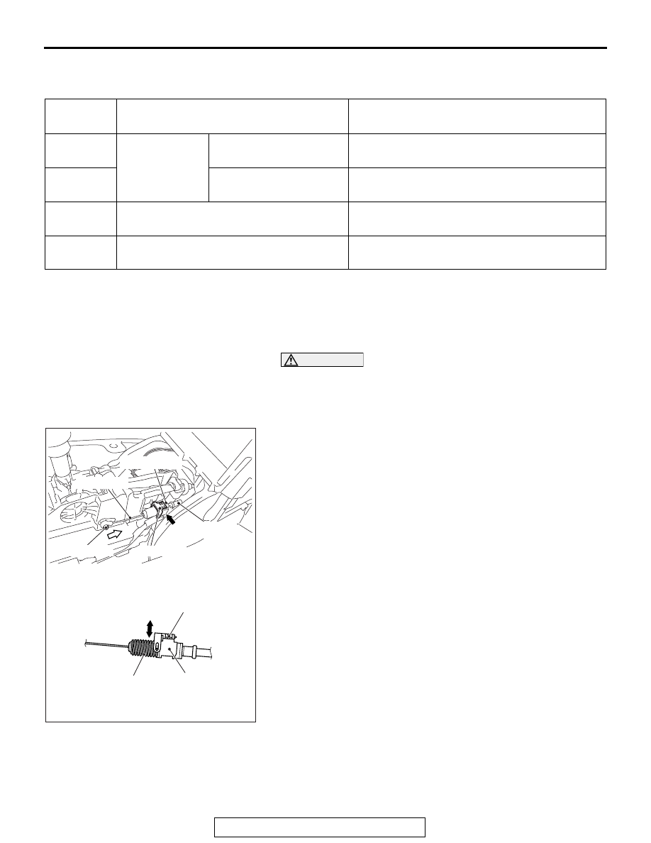
(3) Install the tip of key interlock cable to the lock cam of shift 

lever assembly, using a caution not to twist the inner 
cable.

(4) Install the adjuster case with its lock guide pulled up 

(unlocked).

(5) With the lock cam pin pushed in the direction B as shown 

in the figure to remove the slack from the key interlock 
cable, securely lower the lock guide and lock it.
NOTE: The lock position of the key interlock cable is 
automatically adjusted by a spring.

Inspection 
procedure

Check conditions

Items to be checked (Normal status)

1

Brake pedal: 
Depressed

Ignition switch position: 
LOCK (OFF) or ACC

The shift lever cannot be moved out of the P 
position.

2

Ignition switch position: 
ON

The shift lever can be moved from the P position 
to other positions smoothly.

3

Shift lever position: Other than P

The ignition switch cannot be turned to the 
LOCK (OFF) position.

4

Shift lever position: P

The ignition switch can be turned to the LOCK 
(OFF) position smoothly.

AC900053

View A

Key inter
lock cable

A

Adjuster case

Inner cable

Lock guide

AC

Spring

Lock

Adjuster case

Lock guide

Unlock

B

Lock cam pin

ON-VEHICLE SERVICE

TSB Revision

TWIN CLUTCH- SPORTRONIC SHIFT TRANSMISSION (TC-SST)

22C-402

SHIFT LOCK MECHANISM CHECK

M1225008600128

SYSTEM CHECK

COMPONENTS CHECK

1. Troubleshoot the shift lever.
2. Remove the shift lever assembly. Then, check that there is 

no damage to each part, and that the shift lever can be 
moved to each position.(Refer to 

P.22C-404

.)

3. After performing the check above, if an abnormality is found, 

replace the shift lever assembly.

FLUID CHECK

M1225008700017

Refer to GROUP 27 − On-vehicle Service 

P.27-28

.

BLEEDING

M1225008800014

Refer to GROUP 22A − On-vehicle Service 

P.22A-119

.

ACD OPERATION CHECK

M1225008900011

Refer to GROUP 22A − On-vehicle Service 

P.22A-120

.

Inspection 
procedure

Check conditions

Items to be checked 
(Normal status)

Possible cause of abnormality

1

Release the 
brake pedal.

Ignition switch 
position: LOCK 
(OFF) or ACC

The shift lever cannot be 
moved out of the P 
position.

• Shift lever assembly 

abnormality (seizure, damage, 
or others)

• Electrical circuit abnormality 

(short circuit in solenoid or 
wiring harness)

• Key interlock mechanism 

abnormality

2

Depress the 
brake pedal.

• Shift lever assembly 

abnormality (seizure, damage, 
or others)

• Key interlock mechanism 

abnormality

3

Release the 
brake pedal.

Ignition switch 
position: ON

• Shift lever assembly 

abnormality (seizure, damage, 
or others)

• Electrical circuit abnormality 

(short circuit in solenoid or 
wiring harness)

4

Depress the 
brake pedal.

The shift lever can be 
moved from the P 
position to other positions 
smoothly.

• Shift lever assembly 

abnormality (seizure, damage, 
or others)

• Electrical circuit abnormality 

(open circuit in solenoid or 
wiring harness)

TWIN CLUTCH SST CONTROL MODE SWITCH

TSB Revision

TWIN CLUTCH- SPORTRONIC SHIFT TRANSMISSION (TC-SST)

22C-403

HYDRAULIC PRESSURE CHECK

M1225009000011

Refer to GROUP 22A − On-vehicle Service 

P.22A-121

.

TWIN CLUTCH SST CONTROL MODE SWITCH

REMOVAL AND INSTALLATION

M1225009200015

INSPECTION

TWIN CLUTCH SST CONTROL MODE SWITCH 
CHECK

M1225009100018

1. Check the continuity between the connector terminals of 

twin clutch SST control mode switch.

2. When other than above, replace the twin clutch SST control 

mode switch.

AC710482AB

1

2

Removal steps 

1.

Floor console panel assembly 
(Refer to GROUP 52A − Floor 
Console Assembly 

P.52A-10

).

2.

Twin clutch SST control mode 
switch

Terminal 
number

Switch position

Continuity

2 − 3

Operate to direction A, 
then hold.

Yes (2 Ω or 

less)

Other than above

Not 
present

1 − 3

Operate to direction B, 
then hold.

Yes (2 Ω or 

less)

Other than above

Not 
present

AC708087AD

Twin clutch
SST control
mode switch

Bracket

A

B

TRANSMISSION CONTROL

TSB Revision

TWIN CLUTCH- SPORTRONIC SHIFT TRANSMISSION (TC-SST)

22C-404

TRANSMISSION CONTROL

REMOVAL AND INSTALLATION

M1225009600198

CAUTION

When the transaxle control cable is disconnected, check after the installation that the cable is prop-
erly connected, and that the parking lock mechanism operates normally. At this time, do not check by 
simply using the display on the combination meter and shift indicator panel. Always check according 
to the procedure below.

• With the P range, the vehicle does not move on a slight slope or when pushed by hands.
• When driving at 5 km/h (3.1 mph) or less, the vehicle stops when the shift lever is moved to the P 

range.

Post-installation Operation
• Key interlock mechanism check (Refer to 

P.22C-401

.)

• Shift lock mechanism check (Refer to 

P.22C-402

.)

• Shift lever operation check (Refer to 

P.22C-400

.)

AC902576

1

2

9

8

4

5

7

6

AB

7.0 ± 3.0 N·m
62 ± 26 in-lb

9.5 ± 3.5 N·m
85 ± 30 in-lb

11 ± 4 N·m
98 ± 35 in-lb

3

10

Shift lever assembly 
removal steps 

1. Shift knob
• Floor console bracket (A) 

(Refer to GROUP 52A − Floor 
Console Assembly 

P.52A-10

.)

<<

A

>>

>>

C

<<

2. Pull ring

>>

B

<<

3. Key interlock cable connection 

(shift lever side)

4. Transaxle control cable 

connection (shift lever side)

5. Shift lever-ECU connector 

connection

6. Shift lock solenoid connector 

connection

7. Shift lever assembly

Transaxle control cable 
removal steps 

1. Shift knob

SRS-ECU (Refer to GROUP 
52B − SRS-ECU 

P.52B-410

.)

G and yaw rate sensor and G 
and yaw rate sensor bracket 
(Refer to GROUP 35C − G and 
Yaw Rate Sensor 

P.35C-304

.)

>>

A

<<

4. Transaxle control cable 

connection (shift lever side)

Air cleaner assembly (Refer to 
GROUP 15 − Air Cleaner 

P.15-11

.)

Engine control harness 
connector bracket (Refer to 
GROUP 54A − Battery 

P.54A-10

.)


Content   ..  609  610  611  612   ..