Mitsubishi Lancer Evolution X. Manual - part 587
DIAGNOSIS <TC-SST>
TSB Revision
TWIN CLUTCH- SPORTRONIC SHIFT TRANSMISSION (TC-SST)
22C-305
DTC P2736: Clutch/Shift Switching Solenoid 1 System (Open circuit)
CAUTION
• If there is any problem in the CAN bus lines,
an incorrect diagnostic trouble code may be
set. Prior to this diagnosis, diagnose the CAN
bus lines.
• Whenever the ECU is replaced, ensure that
the CAN bus lines are normal.
.
DIAGNOSTIC FUNCTION
TC-SST-ECU checks that the clutch/shift switching
solenoid 1 circuit is normal.
.
DESCRIPTIONS OF MONITOR METHODS
The clutch/shift switching solenoid 1 circuit is deter-
mined to be open.
.
MONITOR EXECUTION
• Continuous
.
MONITOR EXECUTION CONDITIONS
(OTHER MONITOR AND SENSOR)
Other Monitor (There is no temporary DTC stored
in memory for the item monitored below)
• P2733: Clutch/shift switching solenoid 1, spool
stuck
• P2738: Clutch/shift switching solenoid 1 system
(Short to ground)
• P2739: Clutch/shift switching solenoid 1 system
(Short to power supply)
• P181B: Clutch 1 (Pressure low range out)
• P181C: Clutch 1 (Pressure high range out)
Sensor (The sensor below is determined to be
normal)
• Not applicable
.
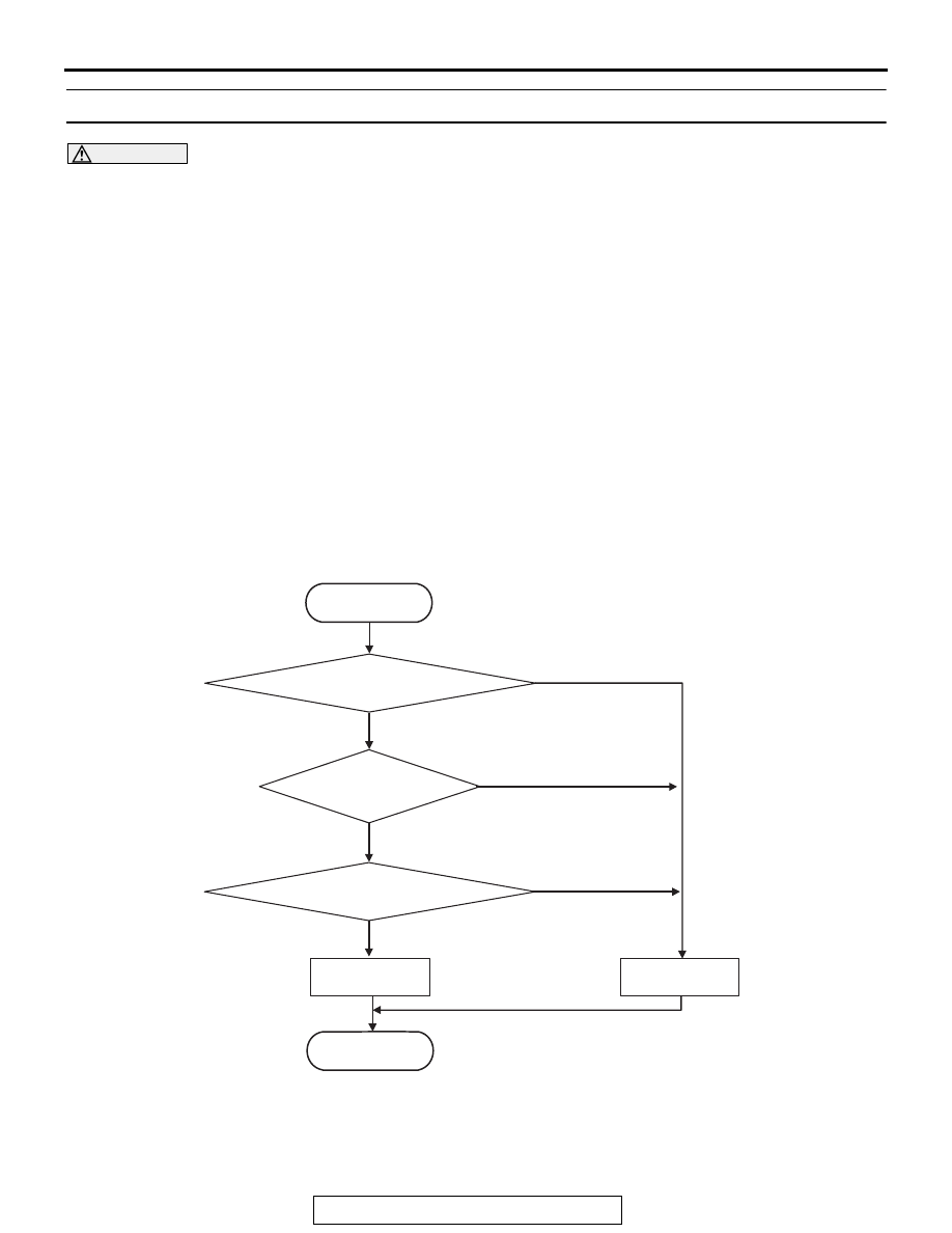
LOGIC FLOW CHARTS (Monitor Sequence)
.
DTC SET CONDITIONS
Check Conditions
• Voltage of battery: 8 V or more.
• Voltage of battery: 16.5 V or less.
JUDGMENT CRITERIA
• FET (Field Effect Transistor) output: 1 V or more.
(400 millisecond)
AC710661
START
No
Good
Malfunction
END
Monitoring condition met
Continuous failure
for 400 msec
No
Yes
Yes
Yes
FET* output > 1 V
No
*FET : Field Effect Transistor