Mitsubishi Lancer Evolution X. Manual - part 536
DIAGNOSIS <TC-SST>
TSB Revision
TWIN CLUTCH- SPORTRONIC SHIFT TRANSMISSION (TC-SST)
22C-101
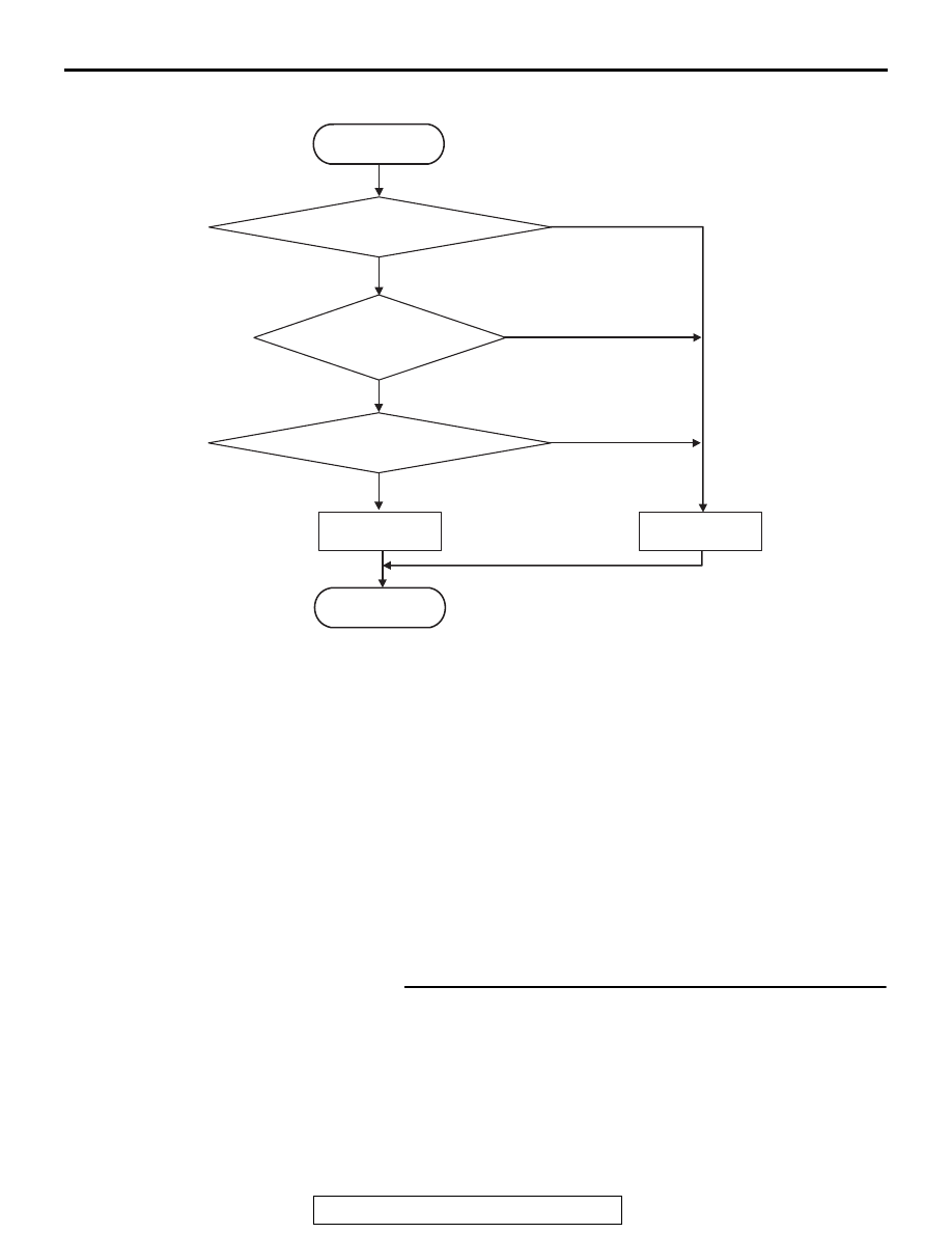
LOGIC FLOW CHARTS (Monitor Sequence)
.
DTC SET CONDITIONS
Check Conditions
• Voltage of battery: 8 V or more.
• Voltage of battery: 16.5 V or less.
JUDGMENT CRITERIA
• Supply voltage: 3.25 V or more. (140 millisecond)
.
OBD-II DRIVE CYCLE PATTERN
The supply voltage remains 3.25 V or less for 140
milliseconds.
.
PROBABLE CAUSES
• Malfunction of TC-SST-ECU
• Malfunction of shift fork position sensor 1 and 2
DIAGNOSTIC PROCEDURE
Required Special Tools:
• MB991958 Scan Tool (M.U.T.-III Sub Assembly)
• MB991824: Vehicle Communication Interface (V.C.I.)
• MB991827 M.U.T.-III USB Cable
• MB991910 M.U.T.-III Main Harness A
STEP 1. Scan tool CAN bus diagnostics
Using scan tool MB991958, diagnose the CAN bus lines.
Q: Is the check result normal?
YES : Go to Step 2.
NO : Repair the CAN bus lines. (Refer to GROUP 54C −
Troubleshooting
.) After repairing the CAN
bus line, go to Step 2.
AC710670
START
No
Good
Malfunction
END
Monitoring condition met
Continuous failure
for 140 msec
No
Yes
Yes
Yes
No
Sensor supply > 3.25 V