Mitsubishi Lancer Evolution X. Manual - part 534


  Index      Mitsubishi     Mitsubishi Lancer Evolution X GS41EVO - service repair manual 2008 year


Search            


Content   ..  532  533  534  535   ..


Mitsubishi Lancer Evolution X. Manual - part 534


DIAGNOSIS <TC-SST>

TSB Revision

TWIN CLUTCH- SPORTRONIC SHIFT TRANSMISSION (TC-SST)

22C-93

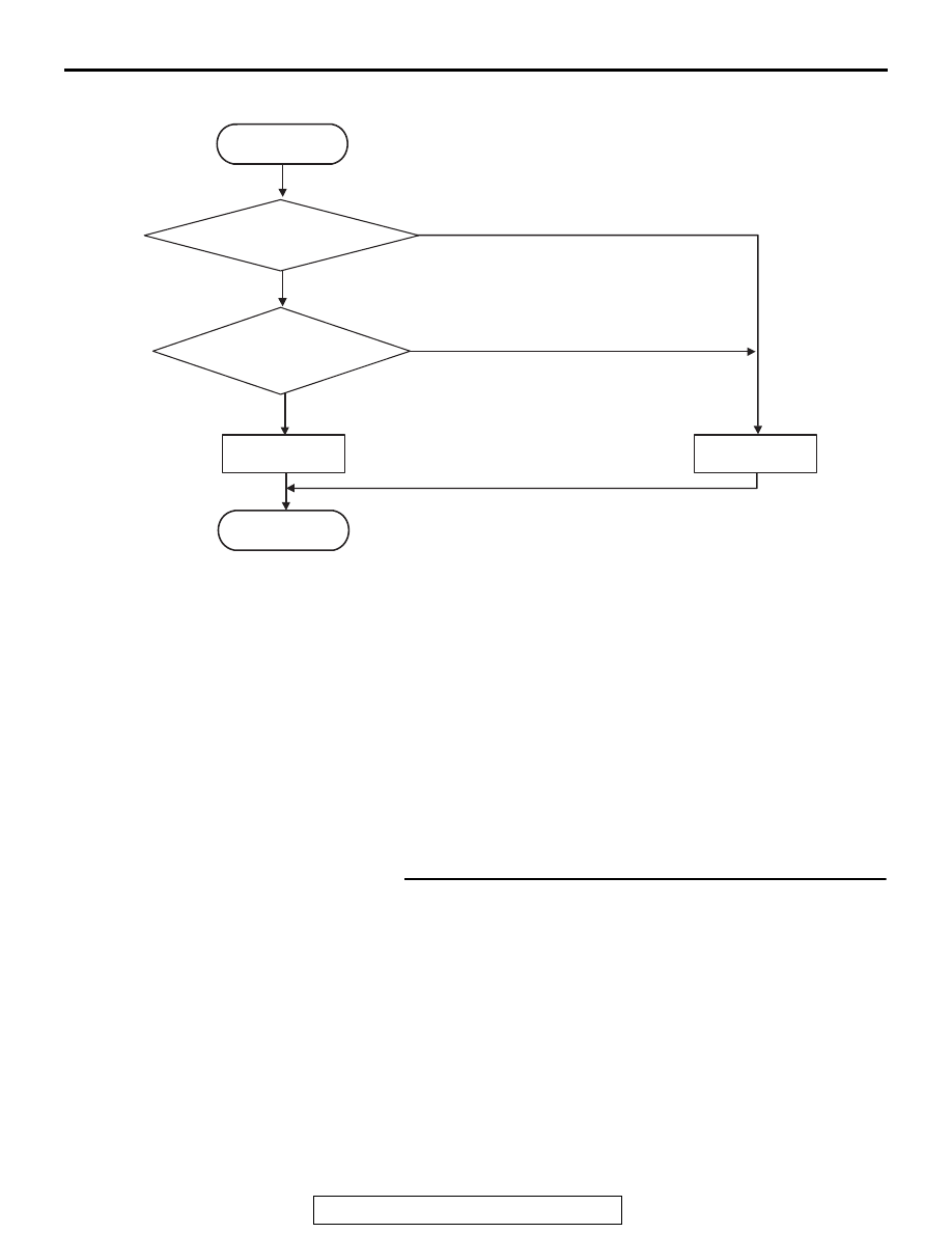
LOGIC FLOW CHARTS (Monitor Sequence)

.

DTC SET CONDITIONS

Check Conditions

• Ignition switch: ON

JUDGMENT CRITERIA

• Coding state: Not programmed. (Immediately)

.

OBD-II DRIVE CYCLE PATTERN

The coding is completed.

.

PROBABLE CAUSES

• Malfunction of TC-SST-ECU

DIAGNOSTIC PROCEDURE

Required Special Tools:

• MB991958 Scan Tool (M.U.T.-III Sub Assembly)

• MB991824: Vehicle Communication Interface (V.C.I.)
• MB991827 M.U.T.-III USB Cable
• MB991910 M.U.T.-III Main Harness A

STEP 1. Scan tool CAN bus diagnostics
Using scan tool MB991958, diagnose the CAN bus lines.
Q: Is the check result normal?

YES : Go to Step 2.
NO :  Repair the CAN bus lines. (Refer to GROUP 54C − 

Troubleshooting 

P.54C-15

.) After repairing the CAN 

bus line, go to Step 2.

AC710730

START

No

Good

Malfunction

END

Yes

Yes

Monitoring condition met

No

Coding state =
not programmed

DIAGNOSIS <TC-SST>

TSB Revision

TWIN CLUTCH- SPORTRONIC SHIFT TRANSMISSION (TC-SST)

22C-94

STEP 2. Check whether the DTC is reset.
After 5 or more seconds have passed with the ignition switch 
ON position, check that the DTC is reset.
Q: Is DTC No. P1676 set?

YES : Perform coding (Refer to the "Scan tool operation 

manual" and perform coding.) or Replace the 
mechatronic assembly (Refer to 

P.22C-421

).

NO :  Intermittent malfunction. (Refer to GROUP 00 − How 

to Cope with Intermittent Malfunction 

P.00-15

.)

DTC P1802: Shift Lever System (LIN communication malfunction)

CPU

SHIFT LEVER

TRANSAXLE ASSEMBLY

NOTE

: THE TERMINAL NUMBERS DESCRIBED 

IN THE CIRCUIT DIAGRAM AGREE WITH 
THE NUMBERS MARKED ON THE 
TRANSAXLE ASSEMBLY CONNECTOR AND 
HARNESS SIDE CONNECTOR.

LIN communication system circuit

AC708949AO

Connector: A-13

AC709137

Connector: B-107

AD

B-107 (B)

DIAGNOSIS <TC-SST>

TSB Revision

TWIN CLUTCH- SPORTRONIC SHIFT TRANSMISSION (TC-SST)

22C-95

CAUTION

• If there is any problem in the CAN bus lines, 

an incorrect diagnostic trouble code may be 
set. Prior to this diagnosis, diagnose the CAN 
bus lines.

• Whenever the ECU is replaced, ensure that 

the CAN bus lines are normal.

.

DIAGNOSTIC FUNCTION

TC-SST-ECU checks that the CAN back-up commu-
nication (LIN) is normal.

.

DESCRIPTIONS OF MONITOR METHODS

The CAN back-up communication is determined to 
be abnormal.

.

PROBABLE CAUSES

• Malfunction of the shift lever-ECU
• Malfunction of the LIN bus
• Malfunction of TC-SST-ECU

DIAGNOSTIC PROCEDURE

Required Special Tools:

• MB991958 Scan Tool (M.U.T.-III Sub Assembly)

• MB991824: Vehicle Communication Interface (V.C.I.)
• MB991827 M.U.T.-III USB Cable
• MB991910 M.U.T.-III Main Harness A

STEP 1. Scan tool CAN bus diagnostics
Using scan tool MB991958, diagnose the CAN bus lines.
Q: Is the check result normal?

YES : Go to Step 2.
NO :  Repair the CAN bus lines. (Refer to GROUP 54C − 

Troubleshooting 

P.54C-15

.) After repairing the CAN 

bus line, go to Step 2.

STEP 2. Scan tool diagnostic trouble code
Check the shift lever diagnostic trouble code. (Refer to 

P.22C-370

.)

Q: Is the DTC set?

YES : Perform the relevant troubleshooting.
NO :  Go to Step 3.

AC705170AM

Connector: C-27

DIAGNOSIS <TC-SST>

TSB Revision

TWIN CLUTCH- SPORTRONIC SHIFT TRANSMISSION (TC-SST)

22C-96

STEP 3. Inspection of the TC-SST-ECU connector, 
intermediate connector, and shift lever-ECU connector: 
B-107, A-13, C-27
Check for the contact with terminals.
Q: Is the check result normal?

YES : Go to Step 4.
NO :  Repair the defective connector.

STEP 4. Check the wiring harness between B-107 
TC-SST-ECU connector terminal No. 17 and C-27 shift 
lever-ECU connector terminal No. 16.
Check the communication line for open and short circuit.
Q: Is the check result normal?

YES : Go to Step 5.
NO :  Repair the wiring harness.

STEP 5. Check whether the DTC is reset.
10 seconds after turning ON the ignition switch, check that the 
DTC is reset.
Q: Is DTC No. P1802 set?

YES : Go to Step 6.
NO :  This diagnosis is complete.

STEP 6. Replace the shift lever assembly, and check if the 
diagnostic trouble code is reset.
(1) Replace the shift lever assembly. (Refer to 

P.22C-404

.)

(2) Check the DTC.
(3) After 10 or more seconds have passed with the ignition 

switch ON position, check that the DTC is reset.

Q: Is DTC No. P1802 set?

YES : Replace the mechatronic assembly. (Refer to 

P.22C-421

.)

NO :  Intermittent malfunction. (Refer to GROUP 00 − How 

to Cope with Intermittent Malfunction 

P.00-15

.)

DTC P1803: Shift Lever System (CAN, LIN Time-out Error)

.

SHIFT LEVER SYSTEM CIRCUIT

Refer to 

P.22C-94

.

CAUTION

• If there is any problem in the CAN bus lines, 

an incorrect diagnostic trouble code may be 
set. Prior to this diagnosis, diagnose the CAN 
bus lines.

• Whenever the ECU is replaced, ensure that 

the CAN bus lines are normal.

.

DIAGNOSTIC FUNCTION

TC-SST-ECU checks that the communication with 
the shift lever-ECU (CAN and LIN) is normal.

.

DESCRIPTIONS OF MONITOR METHODS

The CAN and LIN communication with the shift 
lever-ECU is determined to be abnormal.

.

PROBABLE CAUSES

• Malfunction of the shift lever-ECU
• Malfunction of the LIN bus
• The CAN bus line is defective.
• Malfunction of TC-SST-ECU


Content   ..  532  533  534  535   ..