Mitsubishi Lancer Evolution X. Manual - part 508


  Index      Mitsubishi     Mitsubishi Lancer Evolution X GS41EVO - service repair manual 2008 year


Search            


Content   ..  506  507  508  509   ..


Mitsubishi Lancer Evolution X. Manual - part 508


TRANSAXLE CONTROL

TSB Revision

MANUAL TRANSAXLE

22A-125

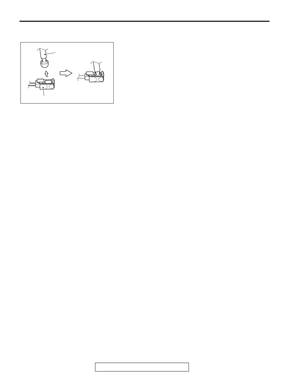
>>B<< SHIFT CABKE CONNECTION (SHIFT 
LEVER SIDE)

To the area of shift lever assembly shown in the figure, securely 
insert the shift cable tip until it clicks into place.

AC607793

Shift cable

Shift lever assembly

AD

TRANSFER ASSEMBLY

TSB Revision

MANUAL TRANSAXLE

22A-126

TRANSFER ASSEMBLY

REMOVAL AND INSTALLATION

M1221003200480

Pre-removal Operation
• Engine Room Under Cover Front B Assembly Removal 

(Refer to GROUP 51, Under Cover 

P.51-15

.)

• Transfer Oil Draining (Refer to 

P.22A-119

.)

Post-installation Operation
• ACD Air Bleeding (Refer to 

P.22A-119

.)

• Transfer Oil Supplying (Refer to 

P.22A-119

.)

• Engine Room Under Cover Front B Assembly Installation 

(Refer to GROUP 51, Under Cover 

P.51-15

.)

AC707652

4

3

12

5

11

6

9

8

10

1

2

AF

Gear oil:
DiaQueen LSD 
gear oil

2

Fluid:
DIAMOND 
ATF SP III

13

N

N

7

25 ± 4 N·m
19 ± 3 ft-lb

10 ± 2 N·m
89 ± 17 in-lb

10 ± 2 N·m
89 ± 17 in-lb

9 ± 1 N·m
80 ± 8 in-lb

10 ± 3 N·m
89 ± 26 in-lb

5.0 ± 2.0 N·m
45 ± 17 in-lb

20 ± 5 N·m
15 ± 3 ft-lb

45 ± 6 N·m
33 ± 4 ft-lb

54 ± 5 N·m
40 ± 3 ft-lb

47 ± 11 N·m
35 ± 8 ft-lb

53 ± 8 N·m
40 ± 5 ft-lb

69 ± 9 N·m
51 ± 7 ft-lb

69 ± 9 N·m
51 ± 7 ft-lb

69 ± 9 N·m
51 ± 7 ft-lb

<OILED>
26 ± 4 N·m
20 ± 2 ft-lb

<DRIED>
34 ± 5 N·m
26 ± 3 ft-lb

44 ± 5 N·m
33 ± 3 ft-lb

13

Removal Steps 

1.

Front floor backbone brace

<<

A

>>

2.

Front propeller shaft 
assembly

Front drive shaft assembly 
and output shaft assembly 
(Refer to GROUP 26, 
Driveshaft Assembly 

P.26-15

.)

Centermember and front roll 
stopper assembly (Refer to 
GROUP 32, Engine Roll 
Stopper and Centermember 

P.32-8

.)

Front exhaust pipe (Refer to 
GROUP 15, Exhaust Pipe 
and Main Muffler 

P.15-26

.)

3.

Rear roll stopper center bolt

4.

Dynamic damper

5.

Drive shaft heater protector

6.

Transfer heater protector

Removal Steps 

TRANSFER ASSEMBLY

TSB Revision

MANUAL TRANSAXLE

22A-127

REMOVAL SERVICE POINT

.

<<A>> FRONT PROPELLER SHAFT ASSEMBLY 
REMOVAL

Make mating marks on the front propeller shaft assembly and 
companion flange, then remove the connecting nut.

.

<<B>> TRANSFER ASSEMBLY REMOVAL

Move the engine and transaxle assembly toward the front of 
the vehicle to create a gap between the engine/transaxle 
assembly and the crossmember. Pull out the transfer assembly 
through this gap.

INSTALLATION SERVICE POINT

.

>>A<< TRANSFER PRESSURE HOSE ASSEMBLY 
INSTALLATION

CAUTION

When installing the transfer pressure hose assembly, use 
caution that the assembly does not interfere with sur-
rounding components.

7.

Transfer pressure hose 
assembly connection

8.

Steering gear and linkage 
heat protector

9.

Turbocharger protector A

<<

B

>>

10. Transfer assembly

>>

A

<<

11. Transfer pressure hose 

assembly

12. Gasket
13. O-ring

Removal Steps 

AC708894AC

Mating marks

TRANSAXLE ASSEMBLY

TSB Revision

MANUAL TRANSAXLE

22A-128

TRANSAXLE ASSEMBLY

REMOVAL AND INSTALLATION

M1221002701139

Pre-removal Operation
• Engine Room Under Cover Front B Assembly, Engine 

Room Side Cover Removal (Refer to GROUP 51, Under 

Cove

P.51-15

.)

• Transmission Oil Draining (Refer to 

P.22A-117

.)

• Engine Upper Cover Removal (Refer to GROUP 16, Igni-

tion Coil 

P.16-40

.)

• Air Cleaner Assembly, Air Cleaner Bracket Removal 

(Refer to GROUP 15, Air Cleaner 

P.15-11

.)

• Headlight Support Panel Cover Removal (Refer to 

GROUP 51, Front Bumper Assembly and Radiator Grille 

P.51-3

.)

• Engine Control Harness Connector Bracket Removal 

(Refer to GROUP 54A, Battery 

P.54A-10

.)

• Radiator Cap Assembly Mounting Bolt, Radiator Con-

denser Tank, Radiator Condenser Tank Bracket Removal 

(Refer to GROUP 14, Radiator 

P.14-32

.)

• Relay box mounting bolt removal
• Front Exhaust Pipe Removal (Refer to GROUP 15, 

Exhaust Pipe and Main Muffler 

P.15-26

.)

• Water pump pulley Removal (Refer to GROUP 14, Water 

pump 

P.14-26

.)

Post-installation Operation
• Water pump pulley Installation (Refer to GROUP 14, 

Water pump 

P.14-26

.)

• Front Exhaust Pipe Installation (Refer to GROUP 15, 

Exhaust Pipe and Main Muffler 

P.15-26

.)

• Relay Box Mounting Bolt Installation
• Radiator Cap Assembly Mounting Bolt, Radiator Con-

denser Tank, Radiator Condenser Tank Bracket Installa-

tion (Refer to GROUP 14, Radiator 

P.14-32

).

• Engine Control Harness Connector Bracket Installation 

(Refer to GROUP 54A, Battery 

P.54A-10

.)

• Headlight Support Panel Cover Installation (Refer to 

GROUP 51, Front Bumper Assembly and Radiator Grille 

P.51-3

.)

• Air Cleaner Assembly, Air Cleaner Bracket Installation 

(Refer to GROUP 15, Air Cleaner 

P.15-11

.)

• Engine Upper Cover Installation (Refer to GROUP 16, 

Ignition Coil 

P.16-40

.)

• Transmission Oil Refilling (Refer to 

P.22A-117

.)

• Engine Room Under Cover Front B Assembly, Engine 

Room Side Cover Installation (Refer to GROUP 51, Under 

Cover 

P.51-15

.)

AC707678

92 ± 13 N·m
68 ± 9 ft-lb

AC707678

2

7

8

1

11

11

9

13

3

12

AC

5

4

14

15

10

6

Release fork

Release cylinder push rod

95 ± 10 N·m
71 ± 7 ft-lb

51 ± 7 N·m
38 ± 5 ft-lb

50 ± 5 N·m
37 ± 3 ft-lb

50 ± 5 N·m
37 ± 3 ft-lb

47 ± 7 N·m
35 ± 5 ft-lb 

50 ± 5 N·m
37 ± 3 ft-lb

24 ± 4 N·m
18 ± 3 ft-lb

24 ± 4 N·m
18 ± 3 ft-lb

24 ± 4 N·m
18 ± 3 ft-lb

Clutch release
cylinder

51 ± 7 N·m
38 ± 5 ft-lb

92 ± 13 N·m
68 ± 9 ft-lb

36 ± 9 N·m
27 ± 6 ft-lb

Specified grease:
MITSUBISHI genuine grease
PART No. 0101011 or equivalent


Content   ..  506  507  508  509   ..