Mitsubishi Lancer Evolution X. Manual - part 507


  Index      Mitsubishi     Mitsubishi Lancer Evolution X GS41EVO - service repair manual 2008 year


Search            


Content   ..  505  506  507  508   ..


Mitsubishi Lancer Evolution X. Manual - part 507


ON-VEHICLE SERVICE

TSB Revision

MANUAL TRANSAXLE

22A-121

5. Rotate the steering wheel 180°  or more to the right or left, 

and drive the vehicle at 20 km/h or less to check that the 
tight corner braking phenomenon occurs.
NOTE: 

.

The occurrence levels of body vibration and noise 
caused by the tight corner braking phenomenon will dif-
fer depending on the conditions of tire and road surface.

If the tight corner braking phenomenon does not occur, 
the system may have an abnormality. Therefore, check 
the hydraulic pressure.

HYDRAULIC PRESSURE CHECK

M1221011800089

1. Remove the rear wheel (RH), then remove the rear wheel 

splash shield.(Refer to GROUP 42A − Splash shield 

P.42A-12

.)

2. Raise the vehicle.
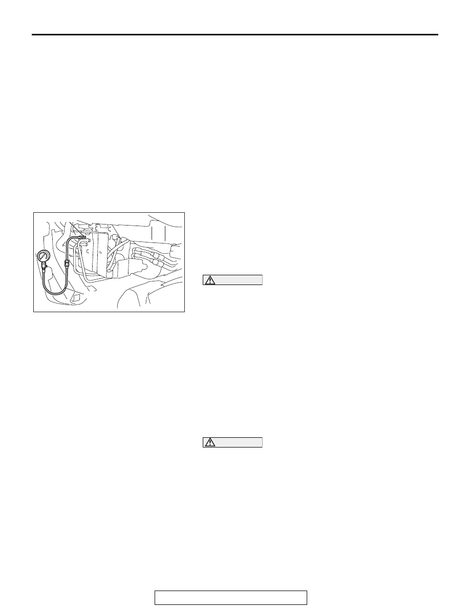
3. Disconnect the hydraulic unit from the ACD pressure tube 

assembly. Then, connect the special tool below to the 
hydraulic unit side.

• Hose adapter (MB991705)
• Oil pressure gauge (MD998330)

4. Bleed the system. (Refer to 

P.22C-402

.)

CAUTION

Before connecting or disconnecting scan tool, always turn 
the ignition switch to the LOCK (OFF) position.
5. Connect scan tool to the data link connector. (Refer to 

P.22A-9

.)

6. Turn the ignition switch to the "ON" position.
7. Perform the actuator test (item No. 05) of scan tool to 

forcibly activate ACD.
NOTE: 

.

The forced activation (item No. 05: ACD operation check 
mode) is continued for 1 minute, then it will be canceled 
automatically. Also, using the clear key on the scan tool, 
the activation can be forcibly canceled.

When the ACD functions are stopped due to the 
fail-safe, the forced activation cannot be performed.

CAUTION

During the hydraulic pressure check, fill the fluid so that 
the fluid constantly remains in the oil reservoir.
8. Check that the generated hydraulic pressure of the hydraulic 

unit is within the standard value.

Standard valve: 0.9  1.1 MPa (130  159 psi)

9. If the measured value exceeds the standard value, replace 

the hydraulic unit.

10.After applying oil to the flare nut thread of ACD pressure 

tube assembly, connect the assembly to the hydraulic unit, 
then tighten to the specified torque.

Tightening torque: 26 ± 4 N⋅ m (19 ± 3 ft-lb)

11.Perform the air bleeding. (Refer to 

P.22A-119

.)

AC707692AC

MB991705

MD998330

TRANSAXLE CONTROL

TSB Revision

MANUAL TRANSAXLE

22A-122

TRANSAXLE CONTROL

REMOVAL AND INSTALLATION

M1221003801106

AC705547

N

1

2

12

11

10

3

4

5

9

6

AC

8

7

7.0 ± 3.0 N·m
62 ± 26 in-lb

9.5 ± 3.5 N·m
85 ± 30 in-lb

Shift lever assembly 
removal steps 

1. Shift knob

Floor console bracket (A) 
(Refer to GROUP 52A, Floor 
console assembly 

P.52A-10

.)

2. Select cable connection (shift 

lever side)

>>

B

<<

3. Shift cable connection (shift 

lever side)

4. Harness clip connection
5. Connector connection
6. Shift lever assembly

Shift cable and select cable 
assembly removal steps 

1. Shift knob

SRS-ECU (Refer to GROUP 
52B, SRS-ECU 

P.52B-410

.)

G and yaw rate sensor and G 
and yaw rate sensor bracket 
(Refer to GROUP 35C − G and 
Yaw Rate Sensor 

P.35C-304

.)

2. Select cable connection (shift 

lever side)

>>

B

<<

3. Shift cable connection (shift 

lever side)

Air cleaner assembly (Refer to 
GROUP 15, Air cleaner 

P.15-11

.)

Engine control harness 
connector bracket (Refer to 
GROUP 54A, Battery 

P.54A-10

.)

7. Snap pin
8. Washer
9. Shift cable connection 

(transaxle side)

<<

A

>>

>>

A

<<

10. Select cable connection 

(transaxle side)

<<

A

>>

>>

A

<<

11. Clip
12. Shift cable and select cable 

assembly

Shift cable and select cable 
assembly removal steps 

TRANSAXLE CONTROL

TSB Revision

MANUAL TRANSAXLE

22A-123

REMOVAL SERVICE POINT

.

<<A>> SELECT CABLE CONNECTION (TRAN-
SAXLE SIDE) / CLIP REMOVAL

1. Set the select cable clips to a status shown in the figure, 

then disconnect the cable.

2. Push down the clip claw using a screwdriver or others. 

Then, remove the clip together with the cable from the 
bracket.

AC707727

Clip

Select cable

AC

AC210556

Clip

Shift cable, 
select cable

Claws

AE

TRANSAXLE CONTROL

TSB Revision

MANUAL TRANSAXLE

22A-124

INSTALLATION SERVICE POINTS

.

>>A<< CLIP/SHIFT CABLE CONNECTION (TRAN-
SAXLE SIDE)/SELECT CABLE CONNECTION 
(TRANSAXLE SIDE) INSTALLATION

CAUTION

Securely insert the clip, shift cable, and select cable until 
they click into place.
1. After inserting the new clip into the cable bracket, insert the 

shift cable or select cable into the cable bracket.

NOTE: The clip can be installed either with its face side down 
or under side down.

2. After assembling the clip of select cable as shown in the 

figure, connect the cables to the levers.

.

AC210558

Shift cable, select cable

New clip

Cable bracket

AG

AC402309

Clip

AE

Select cable


Content   ..  505  506  507  508   ..