Mitsubishi Lancer Evolution X. Manual - part 463


  Index      Mitsubishi     Mitsubishi Lancer Evolution X GS41EVO - service repair manual 2008 year


Search            


Content   ..  461  462  463  464   ..


Mitsubishi Lancer Evolution X. Manual - part 463


ENGINE COOLING DIAGNOSIS

TSB Revision

ENGINE COOLING

14-7

AC708952

FUSIBLE
LINK

29

FUSIBLE
LINK

28

RADIATOR 
FAN RELAY

FAN 
CONTROL
RELAY

CONDENSER
FAN RELAY

RADIATOR 
FAN 
MOTOR

CONDENSER 
FAN MOTOR

INPUT SIGNAL

ENGINE 
COOLANT 
TEMPERATURE 
SENSOR

CAN DRIVE
CIRCUIT

INTERFACE 
CIRCUIT

ENGINE 
CONTROL 
MODULE

JOINT
CONNECTOR 
(CAN3)

JOINT
CONNECTOR 
(CAN2)

INPUT SIGNAL

·FRONT WHEEL
 SPEED SENSOR
·REAR WHEEL
 SPEED SENSOR

ASC-ECU

INPUT SIGNAL

A/C SWITCH

A/C-ECU

JOINT
CONNECTOR 
(CAN1)

CAN DRIVE
CIRCUIT

INTERFACE 
CIRCUIT

ETACS-ECU

JOINT
CONNECTOR 
(CAN2)

AB

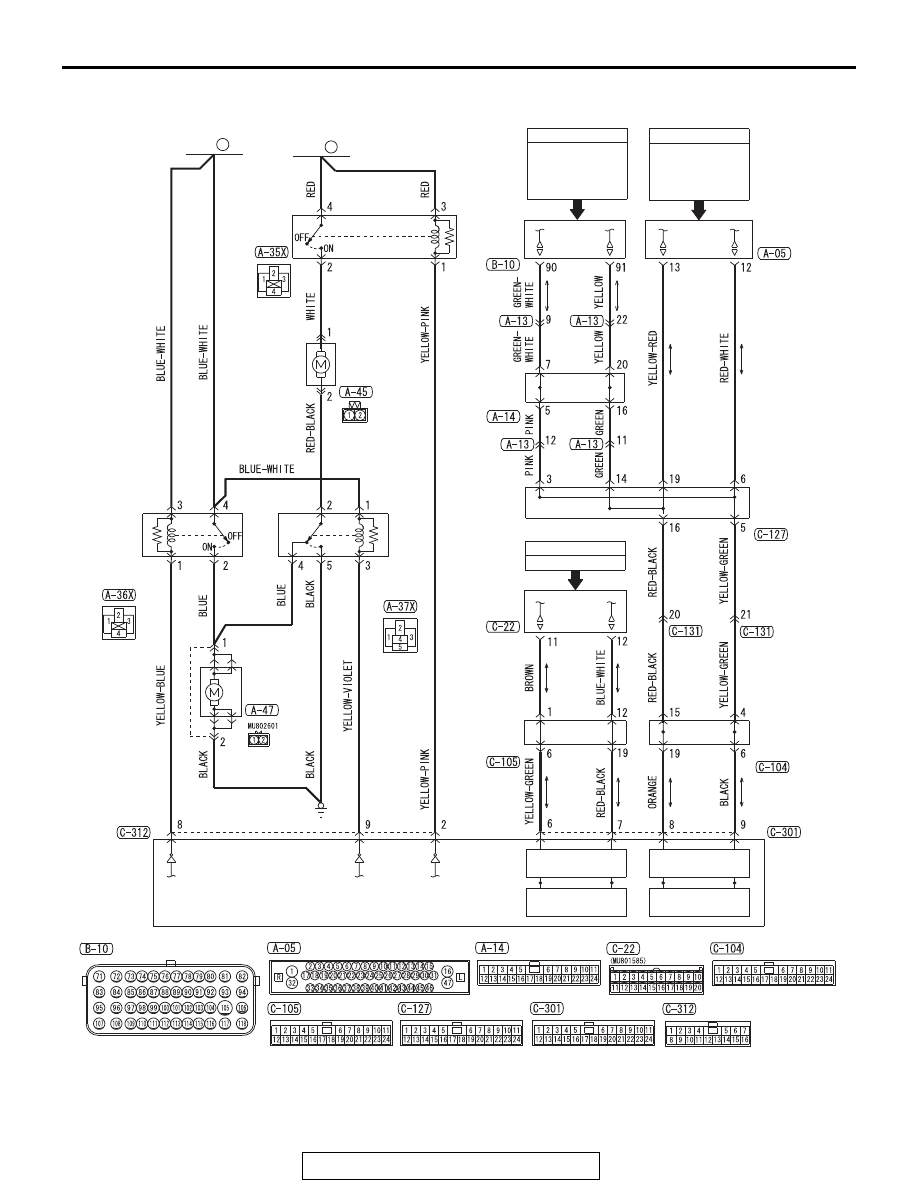
Radiator Fan and Condenser Fan Drive Circuit <TC-SST>

ENGINE COOLING DIAGNOSIS

TSB Revision

ENGINE COOLING

14-8

.

CIRCUIT OPERATION

• The engine control module (ECM) transmits the 

rotation signals of radiator fan and condenser 
fan, based on the engine coolant temperature 
signal from the engine coolant temperature sen-
sor, the vehicle speed signal from the wheel 
speed sensor via the ASC-ECU, and the A/C 
switch signal from the A/C-ECU using the CAN 
bus line.

• The rotation signals of radiator fan and con-

denser fan, using the CAN bus line from ECM, 
turn ON/OFF of the radiator fan relay, condenser 
fan relay, and fan control relay via ETACS-ECU, 
to control the radiator fan and condenser fan rota-
tion.

.

TECHNICAL DESCRIPTION

• When the radiator fan and condenser fan do not 

operate, the wiring harness/connector, fan motor, 
relay, and ETACS-ECU may have a failure.

• The radiator fan and condenser fan do not oper-

ate also when the CAN bus line, MFI system, or 
ETACS system have a failure.

.

TROUBLESHOOTING HINTS

• Malfunction of CAN bus line.
• Damaged wiring harness or connector.
• Malfunction of MFI system.
• Malfunction of ASC system.
• Malfunction of the A/C system.
• Malfunction of ETACS system.
• Malfunction of fusible link number 28.
• Malfunction of fusible link number 29.
• Malfunction of radiator fan relay.
• Malfunction of condenser fan relay.
• Malfunction of fan control relay.
• Malfunction of radiator fan motor.
• Malfunction of condenser fan motor.
• Malfunction of ETACS-ECU.
• Malfunction of ECM.

DIAGNOSTIC PROCEDURE

Required Special Tools:

• MB991958: Scan Tool (M.U.T.-III Sub Assembly)

• MB991824: V.C.I.
• MB991827: M.U.T.-III USB Cable
• MB991910: M.U.T.-III Main Harness A

• MB991223: Harness Set
• MB992006: Extra Fine Probe

AC708833AB

Connectors: A-35X, A-36X, A-37X

A-37X

A-35X

A-36X

Air cleaner

Engine
compartment
relay box

AC708834AB

A-45 (B)

Connectors: A-45, A-47

A-47 (B)

Radiator
assembly

AC708835AB

ETACS-ECU

Connector: C-312

ENGINE COOLING DIAGNOSIS

TSB Revision

ENGINE COOLING

14-9

CAUTION

If there is any problem in the CAN bus lines, an incorrect 
diagnostic trouble code (DTC) may be set. Prior to this 
diagnosis, diagnose the CAN bus lines (Refer to GROUP 
54C, Trouble code diagnosis 

P.54C-9

.)

STEP 1. Using scan tool MB991958, check the CAN bus 
line diagnostics.
Use scan tool to diagnose the CAN bus line (Refer to GROUP 
54C, Explanation About The Scan Tool Can Bus Diagnostics 

P.54C-9

).

Q: Is the diagnostic trouble code set?

YES : Go to Step 2.
NO :  Repair the CAN bus line (Refer to GROUP 54C, 

Diagnosis − Can Bus Diagnostic Table 

P.54C-15

). 

Then go to Step 23.

STEP 2. Using scan tool MB991958, check the MFI system 
actuator test.
Using scan tool to check the MFI system actuator test (Refer to 
GROUP 13A, MFI Diagnosis − Diagnostic Function 

P.13A-9

).

• Item 14: Cooling fan

(Refer to GROUP 13A, MFI Diagnosis − Actuator Test Refer-

ence Table 

P.13A-840

)

Q: Is the check result normal?

YES : Go to Step 22.
NO :  Go to Step 3.

STEP 3. Using scan tool MB991958, read the MFI system 
DTC.
Using scan tool to read the MFI system DTC (Refer to GROUP 
13A, MFI Diagnosis − Diagnostic Function 

P.13A-9

).

Q: Is any DTC set?

YES : Repair the MFI system (Refer to GROUP 13A, MFI 

Diagnosis − Diagnostic Trouble Code Chart 

P.13A-48

). Then go to Step 23.

NO :  Go to Step 4.

STEP 4. Using scan tool MB991958, read the ASC system 
DTC.
Using scan tool to read the ASC system DTC (Refer to GROUP 
35C, Diagnosis − Diagnostic Function 

P.35C-8

.)

Q: Is any DTC set?

YES : Repair the ASC system (Refer to GROUP 35C, 

Diagnosis − Diagnostic Trouble Code Chart 

P.35C-22

.) Then go to Step 23.

NO :  Go to Step 5.

ENGINE COOLING DIAGNOSIS

TSB Revision

ENGINE COOLING

14-10

STEP 5. Using scan tool MB991958, read the A/C system 
DTC.
Using scan tool to read the A/C system DTC (Refer to GROUP 
55, Auto A/C Diagnosis − Diagnostic Functio

P.55-7

.)

Q: Is any DTC set?

YES : Repair the A/C system (Refer to GROUP 55, Auto 

A/C Diagnosis − Diagnostic Trouble Code Chart 

P.55-10

.) Then go to Step 23.

NO :  Go to Step 6.

STEP 6. Using scan tool MB991958, read the ETACS 
system DTC.
Using scan tool to read the ETACS system DTC (Refer to 
GROUP 54A, ETACS, Troubleshooting − Diagnostic Function 

P.54A-643

).

Q: Is any DTC set?

YES : Repair the ETACS system (Refer to GROUP 54A, 

ETACS, Troubleshooting − Diagnostic Trouble Code 

Chart 

P.54A-646

). Then go to Step 23.

NO :  Go to Step 7.

STEP 7. Measure the terminal voltage at ETACS-ECU 
connector C-312.
(1) Disconnect the ETACS-ECU connector C-312, and 

measure at front wiring harness connector side.

(2) Turn the ignition switch to the "ON" position.
(3) Measure the terminal voltage between ETACS-ECU 

connector C-312 terminal number 2 and body ground, 
between ETACS-ECU connector C-312 terminal number 8 
and body ground, and between ETACS-ECU connector 
C-312 terminal number 9 and body ground.

OK: Battery positive voltage

Q: Is the check result normal?

YES : Go to Step 13.
NO :  Go to Step 8.

STEP 8. Check the radiator fan relay connector A-35X, 
condenser fan relay connector A-36X, fan control relay 
connector A-37X, and ETACS-ECU connector C-312, for 
loose, corroded or damaged terminals, or terminals 
pushed back in the connector.
Refer to GROUP 00E, Harness Connector Inspection 

P.00E-2

.

Q: Is the connectors and terminals in good condition?

YES : Go to Step 9.
NO :  Repair or replace the damaged connector. Then go to 

Step 23.

AC708966AB

C-312 Harness connector:
Component side


Content   ..  461  462  463  464   ..