Mitsubishi Lancer Evolution X. Manual - part 448
MULTIPORT FUEL INJECTION (MFI) DIAGNOSIS
TSB Revision
MULTIPORT FUEL INJECTION (MFI)
13A-857
IGNITION COIL AND IGNITION POWER
TRANSISTOR
Required Special Tools:
• MB991658: Test Harness
• MB992110: Power Plant ECU Check Harness
.
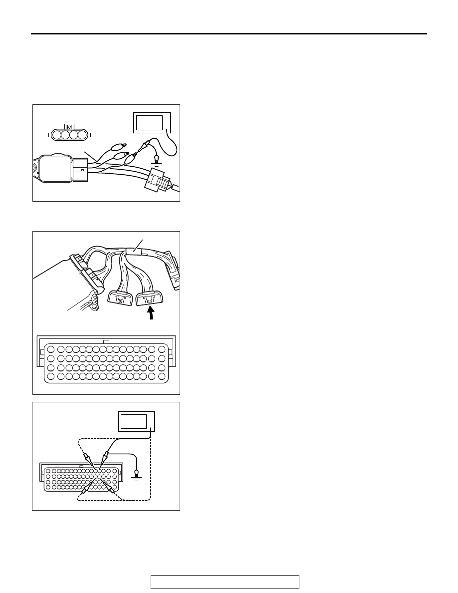
Measurement Method
1. Disconnect the ignition coil connector, and connect test har-
ness special tool (MB991658) between the separated con-
nector. (All terminals should be connected.)
2. Connect the oscilloscope probe to ignition coil connector
terminal No. 2.
.
Alternate method
1. Disconnect all ECM connectors. Connect the check har-
ness special tool (MB992110) between the separated con-
nectors.
2. Connect the oscilloscope probe to each check harness con-
nector terminal to analyze each cylinder:
• Terminal No. 4 for the number 1 cylinder.
• Terminal No. 5 for the number 2 cylinder.
• Terminal No. 20 for the number 3 cylinder.
• Terminal No. 21 for the number 4 cylinder.
AK704387
3 4
2
1
AB
Ignition coil
connector
Oscilloscope
MB991658
16 15 14 13 12 11 10 9 8 7 6 5 4 3
2
1
32 31 30 29 28 27 26 25 24 23 22 21 20 19 18 17
48 47 46 45 44 43 42 41 40 39 38 37 36 35 34 33
64 63 62 61 60 59 58 57 56 55 54 53 52 51 50 49
AK604467AB
Power plant ECU
check harness connector
MB992110
AK704388
16 15 14 13 12 11 10 9 8 7 6 5 4 3
2
1
32 31 30 29 28 27 26 25 24 23 22 21 20 19 18 17
48 47 46 45 44 43 42 41 40 39 38 37 36 35 34 33
64 63 62 61 60 59 58 57 56 55 54 53 52 51 50 49
AB
Oscilloscope
Power plant ECU
check harness
connector