Mitsubishi Lancer Evolution X. Manual - part 431


  Index      Mitsubishi     Mitsubishi Lancer Evolution X GS41EVO - service repair manual 2008 year


Search            


Content   ..  429  430  431  432   ..


Mitsubishi Lancer Evolution X. Manual - part 431


MULTIPORT FUEL INJECTION (MFI) DIAGNOSIS

TSB Revision

MULTIPORT FUEL INJECTION (MFI)

13A-789

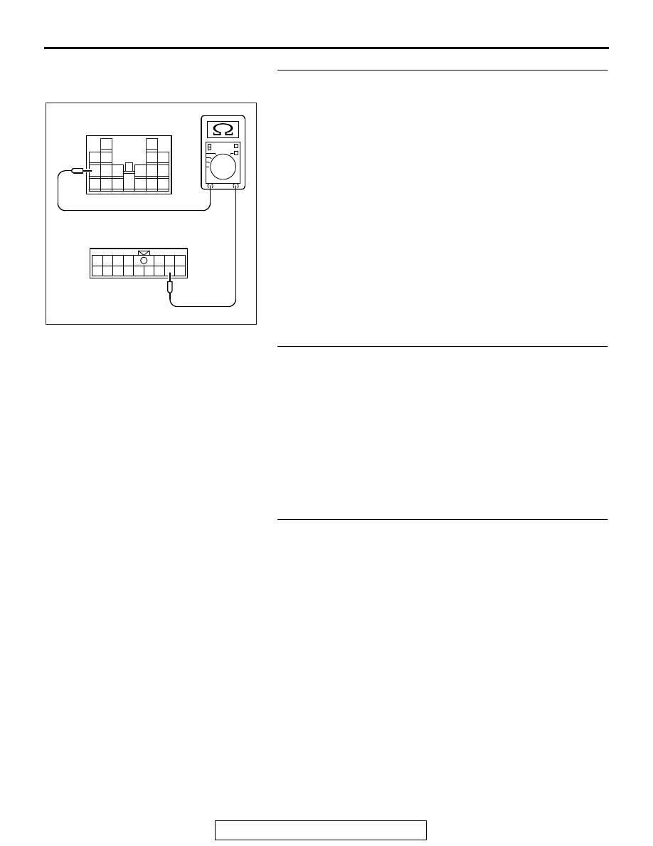
STEP 7. Check for continuity at ETACS-ECU side 
connector C-304 and C-315.
(1) Disconnect the connector C-304, C-315 and measure at the 

ETACS-ECU side.

(2) Measure the resistance between connector C-304 (terminal 

No. 15) and connector C-315 (terminal No. 7).

• Should be less than 2 ohms

Q: Is the harness wire in good condition?

YES : Go to Step 8.
NO :  Replace the ETACS-ECU. Then confirm that the 

malfunction symptom is eliminated.

STEP 8. Check harness connector B-10 ECM connector for 
damage.
Q: Is the connector in good condition?

YES : Repair harness wire between ETACS-ECU connector 

C-304 (terminal No. 15) and ECM connector B-10 
(terminal No. 105) because of open circuit or short 
circuit to ground or harness damage. Then confirm 
that the malfunction symptom is eliminated.

NO :  Repair or replace it. Refer to GROUP 00E, Harness 

Connector Inspection 

P.00E-2

. Then confirm that the 

malfunction symptom is eliminated.

STEP 9. Check harness connector A-28X at starter relay 
connector for damage.
Q: Is the connector in good condition?

YES : Go to Step 10.
NO :  Repair or replace it. Refer to GROUP 00E, Harness 

Connector Inspection 

P.00E-2

. Then confirm that the 

malfunction symptom is eliminated.

1

6

4

5

9

8

10 11

13

15

14

12

16

7

2 3

7

3

8

1

4

9

13 14

16

15

10 11 12

17 18 19

2

5 6

AK704319

C-304 ETACS-ECU
side connector

C-315 ETACS-ECU
side connector

AB

MULTIPORT FUEL INJECTION (MFI) DIAGNOSIS

TSB Revision

MULTIPORT FUEL INJECTION (MFI)

13A-790

STEP 10. Check the starter relay.
(1) Remove the starter relay.
(2) Check for continuity between the starter relay terminals No. 

1 and No. 2.

• There should be continuity.

(3) Use jumper wires to connect starter relay terminal No. 2 to 

the positive battery terminal and terminal No. 1 to the 
negative battery terminal.

(4) Check for continuity between the starter relay terminals No. 

3 and No. 4 while connecting and disconnecting the jumper 
wire at the negative battery terminal.

• Should be less than 2 ohms. (Negative battery terminal 

connected)

• Should be open loop. (Negative battery terminal discon-

nected)

(5) Install the starter relay.
Q: Is the measured resistance within the specified range?

YES : Go to Step 11.
NO :  Replace the starter relay. Then confirm that the 

malfunction symptom is eliminated.

STEP 11. Check for continuity at starter relay harness side 
connector A-28X.
(1) Disconnect the connector A-28X and measure at the 

harness side.

(2) Check for the continuity between terminal No. 1 and 

ground.

• Should be less than 2 ohms.

Q: Does continuity exist?

YES : Go to Step 12.
NO :  Repair harness wire between starter relay connector 

A-28X (terminal No. 1) and ground because of open 
circuit or harness damage. Then confirm that the 
malfunction symptom is eliminated.

AK604033

1

2

3
4

Starter relay side connector

AC

AK604235

1

2

3
4

AC

Starter relay side connector

AK700518

2

1

3
4

AC

A-28X harness
connector:
component side

MULTIPORT FUEL INJECTION (MFI) DIAGNOSIS

TSB Revision

MULTIPORT FUEL INJECTION (MFI)

13A-791

STEP 12. Measure the power supply voltage at starter relay 
harness side connector A-28X.
(1) Disconnect the connector A-28X and measure at the 

harness side.

(2) Turn the ignition switch to the "START" position.
(3) Measure the voltage between terminal No. 2 and ground.

• Voltage should be battery positive voltage

(4) Turn the ignition switch to the "LOCK" (OFF) position.
Q: Is battery positive voltage (approximately 12 volts) 

present?
YES : 
Go to Step 20.
NO :  Go to Step 13.

STEP 13. Check harness connector C-51 at clutch interlock 
switch connector for damage.
Q: Is the connector in good condition?

YES : Go to Step 14.
NO :  Repair or replace it. Refer to GROUP 00E, Harness 

Connector Inspection 

P.00E-2

. Then confirm that the 

malfunction symptom is eliminated.

STEP 14. Check the clutch interlock switch.
Refer to GROUP 21A, Clutch Pedal Check and Master Cylin-
der − Inspection − Interlock Switch Operating Check 

P.21A-8

.

Q: Are there any abnormalities?

YES : Repair or replace it. Then confirm that the malfunction 

symptom is eliminated.

NO :  Go to Step 15.

STEP 15. Measure the power supply voltage at clutch 
interlock switch harness side connector C-51.
(1) Disconnect the connector C-51 and measure at the harness 

side.

(2) Turn the ignition switch to the "START" position.
(3) Measure the voltage between terminal No. 1 and ground.

• Voltage should be battery positive voltage

(4) Turn the ignition switch to the "LOCK" (OFF) position.
Q: Is battery positive voltage (approximately 12 volts) 

present?
YES : 
Go to Step 18.
NO :  Go to Step 16.

AK604216

2

1

3
4

AF

A-28X harness
connector:
component side 

AK704591

2 1

AB

C-51 harness
connector:
component side 

MULTIPORT FUEL INJECTION (MFI) DIAGNOSIS

TSB Revision

MULTIPORT FUEL INJECTION (MFI)

13A-792

STEP 16. Check harness connector B-10 at ECM connector 
for damage.
Q: Is the connector in good condition?

YES : Go to Step 17.
NO :  Repair or replace it. Refer to GROUP 00E, Harness 

Connector Inspection 

P.00E-2

. Then confirm that the 

malfunction symptom is eliminated.

STEP 17. Check for open circuit and short circuit to 
ground between ECM connector B-10 (terminal No. 106) 
and clutch interlock switch connector C-51 (terminal No. 
1).
Q: Is the harness wire in good condition?

YES : Replace the ECM. When the ECM is replaced, 

register the ID code. Refer to GROUP 42B, Diagnosis 
− ID Code Registration Judgment Table <Vehicles with 

KOS> 

P.42B-14

 or GROUP 42C, Diagnosis − ID 

Codes Registration Judgment Table <Vehicles with 
WCM> 

P.42C-10

. Then confirm that the malfunction 

symptom is eliminated.

NO :  Repair it. Then confirm that the malfunction symptom 

is eliminated.

STEP 18. Check for open circuit and short circuit to 
ground between clutch interlock switch connector C-51 
(terminal No. 2) and starter relay A-28X (terminal No. 2).
Q: Is the harness wire in good condition?

YES : Go to Step 19.
NO :  Repair it. Then confirm that the malfunction symptom 

is eliminated.

STEP 19. Check harness connector B-09 at ECM connector 
for damage.
Q: Is the connector in good condition?

YES : Check harness connector A-39 at intermediate 

connector for damage, and repair or replace as 
required. Refer to, GROUP 00E, Harness Connector 
Inspection 

P.00E-2

. If intermediate connector is in 

good condition, repair harness wire between ECM 
connector B-09 (terminal No. 6) and starter relay 
connector A-28X (terminal No. 2) because of short 
circuit to ground. Then confirm that the malfunction 
symptom is eliminated.

NO :  Repair or replace it. Refer to GROUP 00E, Harness 

Connector Inspection 

P.00E-2

. Then confirm that the 

malfunction symptom is eliminated.


Content   ..  429  430  431  432   ..