Mitsubishi Lancer Evolution X. Manual - part 428


  Index      Mitsubishi     Mitsubishi Lancer Evolution X GS41EVO - service repair manual 2008 year


Search            


Content   ..  426  427  428  429   ..


Mitsubishi Lancer Evolution X. Manual - part 428


MULTIPORT FUEL INJECTION (MFI) DIAGNOSIS

TSB Revision

MULTIPORT FUEL INJECTION (MFI)

13A-777

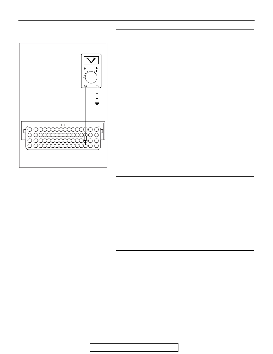
STEP 10. Measure the power supply voltage at ECM 
connector B-09.
(1) Disconnect the connector B-09 and measure at the harness 

side.

(2) Turn the ignition switch to the "ON" position.
(3) Measure the voltage between terminal No. 51 and ground.

• Voltage should be battery positive voltage.

(4) Turn the ignition switch to the "LOCK" (OFF) position.
Q: Is battery positive voltage (approximately 12 volts) 

present?
YES : 
Go to Step 13.
NO :  Go to Step 11.

STEP 11. Check for open circuit and short circuit to ground 
between fuel pump relay 1 connector A-27X (terminal No. 
1) and ECM connector B-09 (terminal No. 51).
NOTE: Check harness after checking intermediate connector 
A-13. If intermediate connector is damaged, repair or replace it. 
Refer to GROUP 00E, Harness Connector Inspection 

P.00E-2

Then check that the malfunction is eliminated.
Q: Is the harness wire in good condition?

YES : Go to Step 12.
NO :  Repair or replace it. Then confirm that the malfunction 

symptom is eliminated.

STEP 12. Check harness connector A-34X at MFI relay for 
damage.
Q: Is the connector in good condition?

YES : Repair harness wire between fuel pump relay 1 

connector (terminal No. 2) and MFI relay connector 
(terminal No. 2) because of open circuit. Then confirm 
that the malfunction symptom is eliminated.

NO :  Repair or replace it. Refer to GROUP 00E, Harness 

Connector Inspection 

P.00E-2

. Then confirm that the 

malfunction symptom is eliminated.

AK704358

16 15 14 13 12 11 10 9 8 7 6 5 4 3

2

1

32 31 30 29 28 27 26 25 24 23 22 21 20 19 18 17

48 47 46 45 44 43 42 41 40 39 38 37 36 35 34 33

64 63 62 61 60 59 58 57 56 55 54 53 52 51 50 49

AB

B-09 harness
connector:
component side

MULTIPORT FUEL INJECTION (MFI) DIAGNOSIS

TSB Revision

MULTIPORT FUEL INJECTION (MFI)

13A-778

STEP 13. Check harness connector D-22 at fuel pump for 
damage.
Q: Is the connector in good condition?

YES : Go to Step 14.
NO :  Repair or replace it. Refer to GROUP 00E, Harness 

Connector Inspection 

P.00E-2

. Then confirm that the 

malfunction symptom is eliminated.

STEP 14. Check the fuel pump operation.
(1)  Disconnect fuel pump connector D-22.
(2)  Use jumper wire to connect fuel pump terminal No. 5 to the 

positive battery terminal and terminal No. 4 the negative 
battery terminal.

• An operating sound of the fuel pump should be heard.

Q: Is the fuel pump operating properly?

YES : Go to Step 15.
NO :  Replace the fuel pump. Then confirm that the 

malfunction symptom in eliminated.

STEP 15. Check for continuity at fuel pump harness side 
connector D-22.
(1) Disconnect the connector D-22 and measure at he harness 

side.

(2)  Check for the continuity between terminal No. 4 and 

ground.

• Should be less than 2 ohms.

Q: Does continuity exist?

YES : Go to Step 16.
NO :  Repair harness wire between fuel pump connector 

D-22 (terminal No. 4) and ground because of open 
circuit and harness damage. Then confirm that the 
malfunction symptom is eliminated.

AK604050

1 2 3

4 5

AB

Fuel pump side
connector

AK604051

1

2

3

4

5

AC

D-22 harness connector:
component side

MULTIPORT FUEL INJECTION (MFI) DIAGNOSIS

TSB Revision

MULTIPORT FUEL INJECTION (MFI)

13A-779

STEP 16. Measurement power supply voltage at fuel pump 
relay harness side connector D-22.
(1)  Disconnect the connector D-22 and measure at the 

harness side.

(2) Disconnect the ECM connector B-10, and connect terminal 

No. 73 and No. 96 to ground using a jumper wire.

(3) Turn the ignition switch to the "ON" position.
(4) Measure the voltage between terminal No. 5 and ground.

• Voltage should be battery positive voltage.

(5) Turn the ignition switch to the "LOCK" (OFF) position.
Q: Is battery positive voltage (approximately 12 volts) 

present?
YES : 
Go to Step 22.
NO :  Go to Step 17.

STEP 17. Check for open circuit and short circuit to 
ground between fuel pump connector D-22 (terminal No. 5) 
and ETACS-ECU connector C-314 (terminal No. 1).
Q: Is the harness wire in good condition?

YES : Go to Step 18.
NO :   Repair or replace it. Then confirm that the 

malfunction symptom is eliminated.

STEP 18. Check for open circuit and short circuit to 
ground between fuel pump circuit resistor connector A-58 
(terminal No. 2) and ETACS-ECU connector C-307 (terminal 
No. 1).
Q: Is the harness wire in good condition?

YES : Go to Step 19.
NO :  Repair or replace it. Then confirm that the malfunction 

symptom is eliminated.

STEP 19. Check harness connector A-34X at MFI relay for 
damage.
Q: Is the connector in good condition?

YES : Go to Step 20.
NO :  Repair or replace it. Refer to GROUP 00E, Harness 

Connector Inspection 

P.00E-2

. Then confirm that the 

malfunction symptom is eliminated.

82 81 80 79 78 77 76 75 74 73 72 71

94 93 92 91 90 89 88 87 86 85 84 83

99 98 97 96 95

100

101

102

103

104

105

106

112

113

114

109 108

107

110

111

115

116

117

118

AK704362 AB

B-10 harness
connector:
component side

AK704363

1

2

3

4

5

AB

D-22 harness
connector:
component side

MULTIPORT FUEL INJECTION (MFI) DIAGNOSIS

TSB Revision

MULTIPORT FUEL INJECTION (MFI)

13A-780

STEP 20. Check for open circuit and short circuit to 
ground between MFI relay connector A-34X (terminal No. 
2) and fuel pump circuit resistor connector A-58 (terminal 
No. 1).
Q: Is the harness wire in good condition?

YES : Go to Step 21.
NO :  Repair or replace it. Then confirm that the malfunction 

symptom is eliminated.

STEP 21. Check for short circuit to ground between fuel 
pump relay 1 connector A-27X (terminal No. 3) and 
ETACS-ECU connector C-307 (terminal No. 1).
Q: Is the harness wire in good condition?

YES : Go to Step 22.
NO :  Repair or replace it. Then confirm that the malfunction 

symptom is eliminated.

STEP 22. Measurement power supply voltage at 
ETACS-ECU harness side connector C-307.
(1)  Disconnect the connector C-307 and measure at the 

harness side.

(2)  Disconnect the ECM connector B-09, and connect terminal 

No. 51 to ground using a jumper wire.

(3) Disconnect the ECM connector B-10, and connect terminal 

No. 73 to ground using a jumper wire.

(4) Turn the ignition switch to the "ON" position.
(5) Measure the voltage between terminal No. 1 and ground.

• Voltage should be battery positive voltage.

(6) Turn the ignition switch to the "LOCK" (OFF) position.
Q: Is battery positive voltage (approximately 12 volts) 

present?
YES : 
Go to Step 27.
NO :  Go to Step 23.

82 81 80 79 78 77 76 75 74 73 72 71

94 93 92 91 90 89 88 87 86 85 84 83

99 98 97 96 95

100

101

102

103

104

105

106

112

113

114

109 108

107

110

111

115

116

117

118

AK704639

16 15 14 13 12 11 10 9 8 7 6 5 4 3

2

1

32 31 30 29 28 27 26 25 24 23 22 21 20 19 18 17

48 47 46 45 44 43 42 41 40 39 38 37 36 35 34 33

64 63 62 61 60 59 58 57 56 55 54 53 52 51 50 49

AB

B-10 harness connector:
component side

B-09 harness connector:
component side

AK704640

1

2

C-307 harness
connector:
component side

AB


Content   ..  426  427  428  429   ..