Mitsubishi Lancer Evolution X. Manual - part 426


  Index      Mitsubishi     Mitsubishi Lancer Evolution X GS41EVO - service repair manual 2008 year


Search            


Content   ..  424  425  426  427   ..


Mitsubishi Lancer Evolution X. Manual - part 426


MULTIPORT FUEL INJECTION (MFI) DIAGNOSIS

TSB Revision

MULTIPORT FUEL INJECTION (MFI)

13A-769

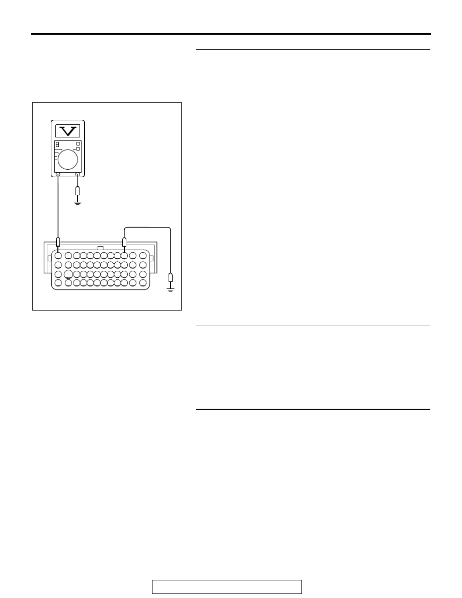
STEP 19. Measure the power supply voltage at ECM 
harness side connector B-10.
(1) Disconnect the connector B-10 and measure at the harness 

side.

(2) Using a jumper wire, connect terminal No. 73 to ground.
(3) Measure the voltage between terminal No. 82 and ground.

• Voltage should be battery positive voltage.

Q: Is battery positive voltage (approximately 12 volts) 

present?
YES : 
Go to Step 22.
NO :  Go to Step 20.

STEP 20. Check for open circuit and short circuit to 
ground between MFI relay connector A-34X (terminal No. 
2) and ECM connector B-10 (terminal No. 73).
Q: Is the harness wire in good condition?

YES : Go to Step 21.
NO :  Repair it. Then confirm that the malfunction symptom 

is eliminated.

STEP 21. Check for harness damage between fusible link 
(36) and MFI relay connector A-34X (terminal No. 3, No. 4).
Q: Is the harness wire in good condition?

YES : Repair harness wire between MFI relay connector 

A-34X (terminal No. 1) and ECM connector (terminal 
No. 73) because of harness damage. Then confirm 
that the malfunction symptom is eliminated.

NO :  Repair it. Then confirm that the malfunction symptom 

is eliminated.

82 81 80 79 78 77 76 75 74 73 72 71

94 93 92 91 90 89 88 87 86 85 84 83

99 98 97 96 95

100

101

102

103

104

105

106

112

113

114

109 108

107

110

111

115

116

117

118

AK704309 AC

B-10 harness
connector:
component side

MULTIPORT FUEL INJECTION (MFI) DIAGNOSIS

TSB Revision

MULTIPORT FUEL INJECTION (MFI)

13A-770

STEP 22. Check for harness damage between MFI relay 
connector A-34X (terminal No. 2) and ECM connector B-10 
(terminal No. 82).
Q: Is the harness wire in good condition?

YES : Replace the ECM. When the ECM is replaced, 

register the ID code. Refer to GROUP 42B, Diagnosis 
− ID Code Registration Judgment Table <Vehicles with 

KOS> 

P.42B-14

 or GROUP 42C, Diagnosis − ID 

Codes Registration Judgment Table <Vehicles with 
WCM> 

P.42C-10

. Then confirm that the malfunction 

symptom is eliminated.

NO :  Repair it. Then confirm that the malfunction symptom 

is eliminated.

MULTIPORT FUEL INJECTION (MFI) DIAGNOSIS

TSB Revision

MULTIPORT FUEL INJECTION (MFI)

13A-771

Inspection procedure 23: Fuel pump system

AK704354

1 2

M

1

3

2

4

1

2 3

4

5

1 2

1 2 3
4 5 6

1 2 3 4

5 6 7

15

14

13

12

11

10

9

8

2

1

1

2

3
4

71 72 73 74 75 76 77 78 79 80 81 82

83 84 85 86 87 88 89 90 91 92 93 94

95 96 97 98 99

100 101 102 103 104

112 113 114

109

108

107

110 111

115 116

106

105

118

117

1

2

3 4 5 6 7 8 9 10 11 12 13 14 15 16

17 18 19 20 21 22 23 24 25 26 27 28 29 30 31 32

33 34 35 36 37 38 39 40 41 42 43 44 45 46 47 48

49 50 51 52 53 54 55 56 57 58 59 60 61 62 63 64

1 2 3 4

5 6 7

12

11

10

15 16

14

13

9

8

2

8

7

6

5

4

3

11

21

20

19

18

17

16

15

14

13

12

9

22

1

10

IG2

ST

LOCK

ACC

IG1

2

TO ECM

5

4

51

BLUE

A-27X

1

C-314

MU801323

A-58

MU802601

C-307

MU801325

C-317

PINK

FUEL PUMP
MODULE

D-22

(MU802058)

FUEL PUMP RELAY 2

FUEL PUMP
RELAY 1

FUEL PUMP
CIRCUIT RESISTOR

ETACS-ECU

B-10

C-304

B-09

A-13

11

96

BLA

CK

20A

A-34X

4

2

3

1

23

OFF

ON

OFF

ON

OFF

ON

FUEL PUMP CIRCUIT

WHITE

IGNITION SWITCH

C-210

AC

WHITE

FUSIBLE LINK

WHITE

BLUE

BLUE

GREEN

GREEN

RED-BLA

CK

RED-BLA

CK

RED-WHITE

RED-

WHITE

36

2

4

1

18

3

1

1

2

6

MFI
RELAY

RELAY BOX
(ENGINE COMPARTMENT)

ENGINE CONTROL MODULE

MULTIPORT FUEL INJECTION (MFI) DIAGNOSIS

TSB Revision

MULTIPORT FUEL INJECTION (MFI)

13A-772

.

CIRCUIT OPERATION

• The power supply is supplied from the MFI relay 

(terminal No. 2) to the fuel pump relay 1 (terminal 
No. 4) and the fuel pump circuit resistor (terminal 
No. 1).

• The battery positive voltage is applied to the fuel 

pump relay 1 (terminal No. 2) from the MFI relay 
(terminal No. 2).

• The battery positive voltage is applied from the 

ignition switch to the fuel pump relay 2 (C-317 
ETACS-ECU connector terminal No. 6).

• The ECM (terminal No. 96) turns ON the power 

transistor of the unit during the engine cranking 
and running. The current is going through the fuel 
pump relay 2 (C-304 ETACS-ECU connector ter-
minal No. 11), and then the relay is turned ON. 

AK704229AB

Connector: A-13

A-13

AK704355 AB

Connectors: A-27X, A-34X

A-27X

MFI relay

Fuel pump relay 1

A-34X

AK704356AB

Connector: A-58

A-58 (B)

Fuel pump
circuit resistor

AK704295AB

B-10 (GR)

B-09 (GR)

ECM

Connectors: B-09, B-10

AK704352AB

Connector: C-210

C-210

AK704357AB

Connectors: C-304, C-307, C-314 and C-317

ETACS-ECU

C-304

C-307 (B)

C-314

C-317

AK704253 AB

Fuel pump module (incorporating 
fuel level sensor (main) and 
fuel tank temperature sensor)

Connector: D-22

D-22 (GR)


Content   ..  424  425  426  427   ..