Mitsubishi Lancer Evolution X. Manual - part 424
MULTIPORT FUEL INJECTION (MFI) DIAGNOSIS
TSB Revision
MULTIPORT FUEL INJECTION (MFI)
13A-761
.
CIRCUIT OPERATION
• Battery positive voltage is applied to the MFI
relay (terminals No. 3, No. 4).
• When the ignition switch is turned to the "ON"
position, battery positive voltage is applied to the
ECM (terminal No. 92). When battery positive
voltage is applied, the ECM turns the power tran-
sistor in the ECM "ON" and grounds the MFI relay
coil. With this, the MFI relay turns "ON" the bat-
tery positive voltage is supplied to the ECM (ter-
minals No. 82) from the MFI relay (terminal No.
2).
• A battery positive voltage is constantly supplied
to the ECM (terminal No. 104) as the backup
power.
• The ECM (terminals No. 81, No. 93) is grounded
to the vehicle body.
.
COMMENT
• When the ignition switch "ON" signal is input into
the ECM via ETACS-ECU, the ECM turns "ON"
the MFI relay. This causes battery positive volt-
age to be supplied to the ECM, sensor and actua-
tor.
.
TROUBLESHOOTING HINTS (The most
likely causes for this case)
• Malfunction of the ignition switch.
• Malfunction of the MFI relay.
• Open of shorted power supply and ignition
Switch-IG circuit, harness damage, or connector
damage.
• Malfunction of the ECM.
AK704226
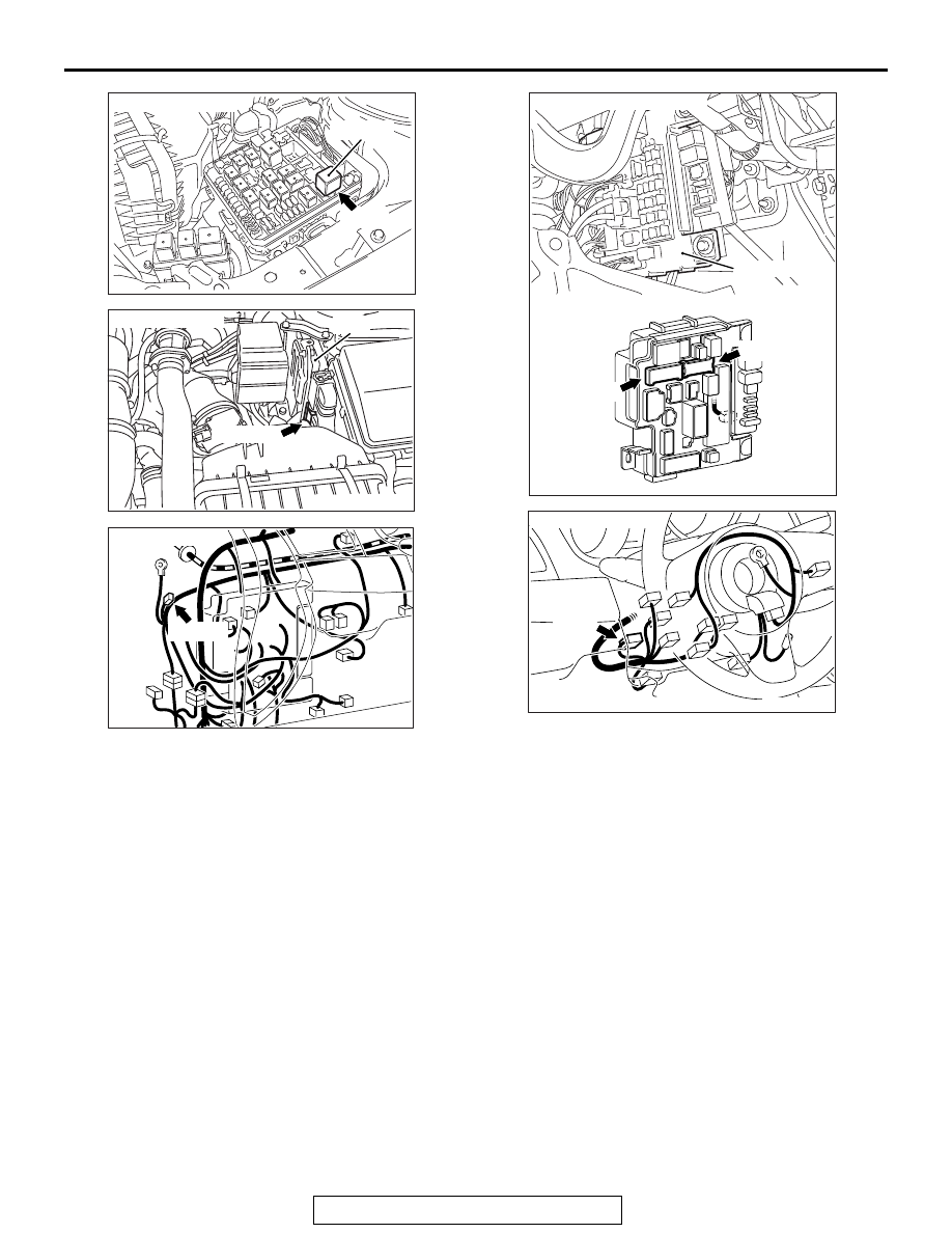
Connector: A-34X
MFI relay
A-34X
AB
AK704235 AB
Connector: B-10
ECM
B-10 (GR)
AK704258 AB
Connector: C-50
C-50 (B)
AK704259AB
Connectors: C-304, C-317
ETACS-ECU
C-304
C-317
AK704352AB
Connector: C-210
C-210