Mitsubishi Lancer Evolution X. Manual - part 399


  Index      Mitsubishi     Mitsubishi Lancer Evolution X GS41EVO - service repair manual 2008 year


Search            


Content   ..  397  398  399  400   ..


Mitsubishi Lancer Evolution X. Manual - part 399


MULTIPORT FUEL INJECTION (MFI) DIAGNOSIS

TSB Revision

MULTIPORT FUEL INJECTION (MFI)

13A-661

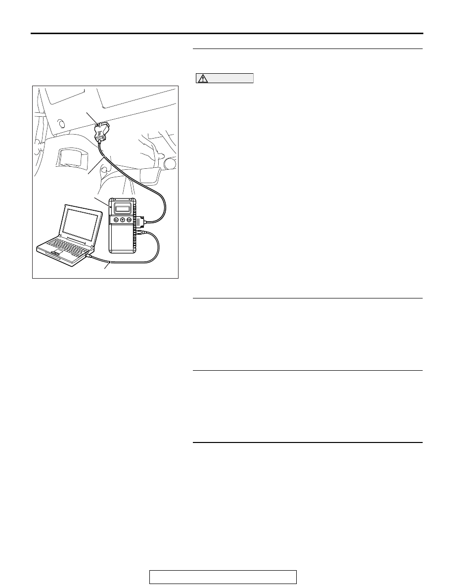
STEP 5. Using scan tool MB991958, read the diagnostic 
trouble code (DTC).

CAUTION

To prevent damage to scan tool MB991958, always turn the 
ignition switch to the "LOCK" (OFF) position before con-
necting or disconnecting scan tool MB991958.
(1) Connect scan tool MB991958 to the data link connector.
(2) Turn the ignition switch to the "ON" position.
(3) Erase the DTC.
(4) Depress the accelerator pedal fully for a few seconds.
(5) Check the DTC.
(6) Turn the ignition switch to the "LOCK" (OFF) position.
Q: Is DTC P2135 set?

YES : Replace the ECM. When the ECM is replaced, 

register the ID code. Refer to GROUP 42B, ID Code 
Registration Necessity Judgment Table <Vehicles 
with KOS> 

P.42B-11

 or GROUP 42C, ID Codes 

Registration Judgment Table <Vehicles with WCM> 

P.42C-9

. Then go to Step 11.

NO :  It can be assumed that this malfunction is intermittent. 

Refer to GROUP 00, How to Use 
Troubleshooting/Inspection Service Points − How to 

Cope with Intermittent Malfunctions 

P.00-15

.

STEP 6. Check harness connector B-09 at ECM for 
damage.
Q: Is the harness connector in good condition?

YES : Go to Step 7.
NO :  Repair or replace it. Refer to GROUP 00E, Harness 

Connector Inspection 

P.00E-2

. Then go to Step 11.

STEP 7. Check for harness damage between throttle 
position sensor connector B-11 (terminal No. 5) and ECM 
connector B-09 (terminal No. 12).
Q: Is the harness wire in good condition?

YES : Go to Step 8.
NO :  Repair it. Then go to Step 11.

STEP 8. Check for harness damage between throttle 
position sensor connector B-11 (terminal No. 4) and ECM 
connector B-09 (terminal No. 10).
Q: Is the harness wire in good condition?

YES : Go to Step 9.
NO :  Repair it. Then go to Step 11.

AC608435

Data link connector

MB991827

MB991824

MB991910

AB

MULTIPORT FUEL INJECTION (MFI) DIAGNOSIS

TSB Revision

MULTIPORT FUEL INJECTION (MFI)

13A-662

STEP 9. Check for harness damage between throttle 
position sensor connector B-11 (terminal No. 6) and ECM 
connector B-09 (terminal No. 11).
Q: Is the harness wire in good condition?

YES : Go to Step 10.
NO :  Repair it. Then go to Step 11.

STEP 10. Replace the throttle body assembly.
(1) Replace the throttle body assembly.
(2) Turn the ignition switch to the "ON" position.
(3) Erase the DTC.
(4) Depress the throttle fully for a few seconds.
(5) Check the DTC.
(6) Turn the ignition switch to the "LOCK" (OFF) position.
Q: Is DTC P2135 set?

YES : Replace the ECM. When the ECM is replaced, 

register the ID code. Refer to GROUP 42B, ID Code 
Registration Necessity Judgment Table <Vehicles 
with KOS> 

P.42B-11

 or GROUP 42C, ID Codes 

Registration Judgment Table <Vehicles with WCM> 

P.42C-9

. Then go to Step 11.

NO :  The inspection is complete.

STEP 11. Using scan tool MB991958, read the diagnostic 
trouble code (DTC).

CAUTION

To prevent damage to scan tool MB991958, always turn the 
ignition switch to the "LOCK" (OFF) position before con-
necting or disconnecting scan tool MB991958.
(1) Connect scan tool MB991958 to the data link connector.
(2) Turn the ignition switch to the "ON" position.
(3) Erase the DTC.
(4) Depress the throttle fully for a few seconds.
(5) Check the DTC.
(6) Turn the ignition switch to the "LOCK" (OFF) position.
Q: Is DTC P2135 set?

YES : Retry the troubleshooting.
NO :  The inspection is complete.

AC608435

Data link connector

MB991827

MB991824

MB991910

AB

MULTIPORT FUEL INJECTION (MFI) DIAGNOSIS

TSB Revision

MULTIPORT FUEL INJECTION (MFI)

13A-663

DTC P2138: Accelerator Pedal Position Sensor (main and sub) Range/Performance Problem

.

ACCELERATOR PEDAL POSITION 
SENSOR (main and sub) 
RANGE/PERFORMANCE PROBLEM 
CIRCUIT

• Refer to DTC P2122 − Accelerator Pedal Position 

Sensor (main) Circuit Low Input 

P.13A-638

.

• Refer to DTC P2127 − Accelerator Pedal Position 

Sensor (sub) Circuit Low Input 

P.13A-648

.

.

CIRCUIT OPERATION

• Refer to DTC P2122 − Accelerator Pedal Position 

Sensor (main) Circuit Low Input 

P.13A-638

.

• Refer to DTC P2127 − Accelerator Pedal Position 

Sensor (sub) Circuit Low Input 

P.13A-648

.

.

TECHNICAL DESCRIPTION

• ECM checks the accelerator pedal position sen-

sor output signal characteristics for abnormal 
conditions.

.

DESCRIPTIONS OF MONITOR METHODS

Detect malfunction if the relation between accelera-

tor pedal position sensor (main) and accelerator 
pedal position sensor (sub) is wrong.

.

MONITOR EXECUTION

Continuous

.

MONITOR EXECUTION CONDITIONS 
(Other monitor and Sensor)

Other Monitor (There is no temporary DTC stored 

in memory for the item monitored below)

• Not applicable

Sensor (The sensor below is determined to be 

normal)

• Not applicable

.

AK704235 AB

Connector: B-10

ECM

B-10 (GR)

AK704296

Accelerator pedal 
position sensor

Accelerator
pedal

AB

C-01 (B)

Connector: C-01

MULTIPORT FUEL INJECTION (MFI) DIAGNOSIS

TSB Revision

MULTIPORT FUEL INJECTION (MFI)

13A-664

DTC SET CONDITIONS <Range/Performance problem -relation between main and 
sub>

Logic Flow Chart

.

Check Conditions

• Change of accelerator pedal position sensor 

(sub) output voltage per 25 milliseconds is lower 
than 0.06 volt.

Judgement Criterion

• Voltage obtained with the formula given below is 

0.4 volt or higher for 0.3 second: [accelerator 
pedal position sensor (sub) voltage − accelerator 

pedal position sensor (main) voltage].

NOTE: The accelerator pedal position sensor 
voltage used for the judgement is converted into 
the accelerator pedal position sensor voltage for 
the internal processing by the ECM.

.

AK604363

Start

Yes

Yes

Yes

No

No

No

{APS (sub) - APS (main)}

>= 0.4V

Continuous

failure for 0.3sec

Malfunction

End

Good

Monitoring
conditions


Content   ..  397  398  399  400   ..