Mitsubishi Lancer Evolution X. Manual - part 397


  Index      Mitsubishi     Mitsubishi Lancer Evolution X GS41EVO - service repair manual 2008 year


Search            


Content   ..  395  396  397  398   ..


Mitsubishi Lancer Evolution X. Manual - part 397


MULTIPORT FUEL INJECTION (MFI) DIAGNOSIS

TSB Revision

MULTIPORT FUEL INJECTION (MFI)

13A-653

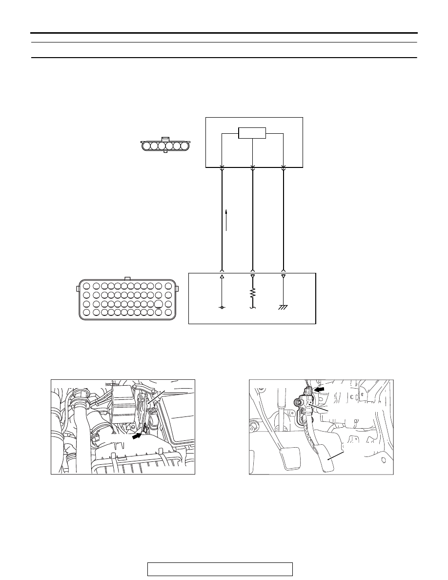
DTC P2128: Accelerator Pedal Position Sensor (sub) Circuit High Input

.

CIRCUIT OPERATION

• A 5-volt power supply is applied on the accelera-

tor pedal position sensor (sub) power terminal 
(terminal No. 4) from the ECM (terminal No. 78).

• A voltage that is according to the accelerator 

opening angle is sent to the ECM (terminal No. 
77) from the accelerator pedal position sensor 
(sub) output terminal (terminal No. 6).

• The ground terminal (terminal No. 5) is grounded 

with ECM (terminal No. 79).

.

AK604257

71 72 73 74 75 76 77 78 79 80 81 82

83 84 85 86 87 88 89 90 91 92 93 94

95 96 97 98 99

100 101 102 103 104

112 113 114

109

108

107

110 111

115 116

106

105

118

117

6

1 2 3 4 5

AH

5 V

78

4

YELLO

W

-RED

YELLO

W

-BLA

CK

BR

O

WN

77

79

6

5

B-10

C-01

HALL IC

ENGINE
CONTROL
MODULE

ACCELERATOR PEDAL POSITION SENSOR (SUB) CIRCUIT

ACCELERATOR PEDAL
POSITION SENSOR (SUB)

AK704235 AB

Connector: B-10

ECM

B-10 (GR)

AK704296

Accelerator pedal 
position sensor

Accelerator
pedal

AB

C-01 (B)

Connector: C-01

MULTIPORT FUEL INJECTION (MFI) DIAGNOSIS

TSB Revision

MULTIPORT FUEL INJECTION (MFI)

13A-654

TECHNICAL DESCRIPTION

• The accelerator pedal position sensor (sub) out-

puts voltage which corresponds to the accelera-
tor pedal depression.

• The ECM checks whether the voltage is within a 

specified range.

.

DESCRIPTIONS OF MONITOR METHODS

Accelerator pedal position sensor (sub) output volt-

age is out of specified range.

.

MONITOR EXECUTION

Continuous

.

MONITOR EXECUTION CONDITIONS 
(Other monitor and Sensor)

Other Monitor (There is no temporary DTC stored 

in memory for the item monitored below)

• Not applicable

Sensor (The sensor below is determined to be 

normal)

• Not applicable

.

DTC SET CONDITIONS
Logic Flow Chart

.

Check Condition

• Ignition switch is "ON" position.

Judgement Criterion

• Accelerator pedal position sensor (sub) output 

voltage is 2.5 volts or higher for 0.3 second.

.

FAIL-SAFE AND BACKUP FUNCTION

• Throttle opening degree is restricted.

• Throttle opening degree position is in default 

position if accelerator pedal position sensor 
(main) fails.

.

OBD-II DRIVE CYCLE PATTERN

None.

.

AK604340

Good

Malfunction

End

No

No

Output voltage >= 2.5V

Start

Yes

Yes

Continuous

failure for 0.3sec

MULTIPORT FUEL INJECTION (MFI) DIAGNOSIS

TSB Revision

MULTIPORT FUEL INJECTION (MFI)

13A-655

TROUBLESHOOTING HINTS (The most 
likely causes for this code to be set are:)

• Accelerator pedal position sensor failed.
• Open accelerator pedal position sensor (sub) cir-

cuit, harness damage or connector damage.

• ECM failed. 

DIAGNOSIS

Required Special Tools:

• MB991958: Scan tool (M.U.T.-III Sub Assembly)

• MB991824: V.C.I.
• MB991827: USB Cable
• MB991910: Main Harness A

STEP 1. Using scan tool MB991958, check data list item 12: 
Accelerator Pedal Position Sensor (sub).

CAUTION

To prevent damage to scan tool MB991958, always turn the 
ignition switch to the "LOCK" (OFF) position before con-
necting or disconnecting scan tool MB991958.
(1) Connect scan tool MB991958 to the data link connector.
(2) Turn the ignition switch to the "ON" position.
(3) Set scan tool MB991958 to the data reading mode for item 

12, Accelerator Pedal Position Sensor (sub).

• Output voltage is between 0.4 and 0.6 volt when foot is 

released from accelerator pedal.

• Output voltage is 2.0 volts or higher when accelerator 

pedal is fully depressed.

(4) Turn the ignition switch to the "LOCK" (OFF) position.
Q: Is the sensor operating properly?

YES : It can be assumed that this malfunction is intermittent. 

Refer to GROUP 00, How to Use 
Troubleshooting/Inspection Service Points − How to 

Cope with Intermittent Malfunctions 

P.00-15

.

NO :  Go to Step 2.

STEP 2. Check harness connector C-01 at accelerator 
pedal position sensor for damage.
Q: Is the harness connector in good condition?

YES : Go to Step 3.
NO :  Repair or replace it. Refer to GROUP 00E, Harness 

Connector Inspection 

P.00E-2

. Then go to Step 8.

AC608435

Data link connector

MB991827

MB991824

MB991910

AB

MULTIPORT FUEL INJECTION (MFI) DIAGNOSIS

TSB Revision

MULTIPORT FUEL INJECTION (MFI)

13A-656

STEP 3. Check the continuity at accelerator pedal position 
sensor harness side connector C-01.
(1) Disconnect the connector C-01 and measure at the harness 

side.

(2) Measure the continuity between terminal No. 5 and ground.

• Continuity (2 ohms or less)

Q: Does continuity exist?

YES : Go to Step 7.
NO :  Go to Step 4.

STEP 4. Check harness connector B-10 at ECM for 
damage.
Q: Is the harness connector in good condition?

YES : Go to Step 5.
NO :  Repair or replace it. Refer to GROUP 00E, Harness 

Connector Inspection 

P.00E-2

. Then go to Step 8.

STEP 5. Check for open circuit and harness damage 
between accelerator pedal position sensor connector C-01 
(terminal No. 5) and ECM connector B-10 (terminal No. 79).
Q: Is the harness wire in good condition?

YES : Go to Step 6.
NO :  Repair it. Then go to Step 8.

STEP 6. Using scan tool MB991958, check data list item 12: 
Accelerator Pedal Position Sensor (sub).
(1) Turn the ignition switch to the "ON" position.
(2) Set scan tool MB991958 to the data reading mode for item 

12, Accelerator Pedal Position Sensor (sub).

• Output voltage is between 0.4 and 0.6 volt when foot is 

released from accelerator pedal.

• Output voltage is 2.0 volts or higher when accelerator 

pedal is fully depressed.

(3) Turn the ignition switch to the "LOCK" (OFF) position.
Q: Is the sensor operating properly?

YES : It can be assumed that this malfunction is intermittent. 

Refer to GROUP 00, How to Use 
Troubleshooting/Inspection Service Points − How to 

Cope with Intermittent Malfunctions 

P.00-15

.

NO :  Replace the ECM. When the ECM is replaced, 

register the ID code. Refer to GROUP 42B, ID Code 
Registration Necessity Judgment Table <Vehicles 
with KOS> 

P.42B-11

 or GROUP 42C, ID Codes 

Registration Judgment Table <Vehicles with WCM> 

P.42C-9

. Then go to Step 8.

AK704745

1

6 5 4 3 2

AB

C-01 harness
connector:
component side 


Content   ..  395  396  397  398   ..