Mitsubishi Lancer Evolution X. Manual - part 363
MULTIPORT FUEL INJECTION (MFI) DIAGNOSIS
TSB Revision
MULTIPORT FUEL INJECTION (MFI)
13A-517
DTC SET CONDITIONS
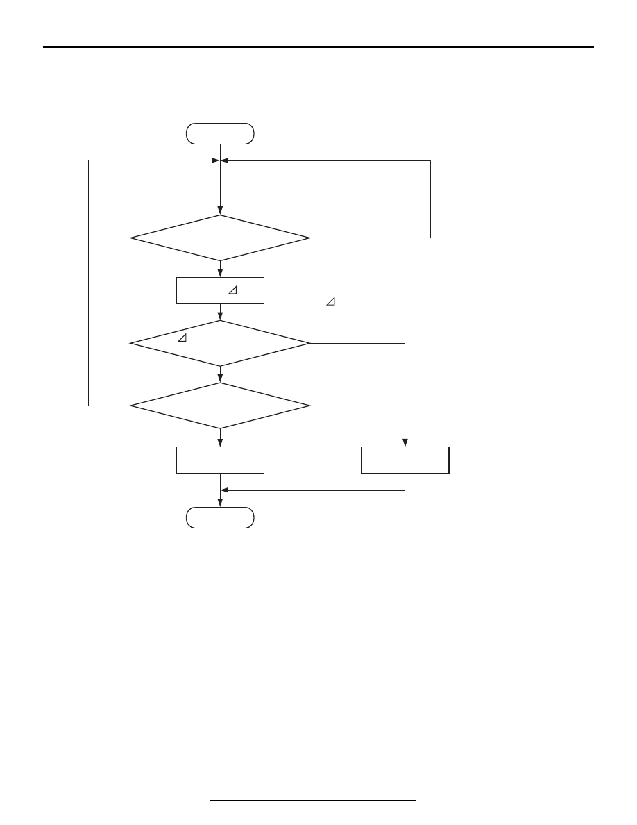
Logic Flow Chart
.
Check Conditions
• Under the closed loop idle speed control.
• The engine coolant temperature is 41° C (105° F)
or more.
• Battery positive voltage is higher than 10 volts.
• Barometric pressure is higher than 76 kPa (22.4
in.Hg).
• Intake air temperature is higher than −10° C
(14° F).
• 3 seconds have elapsed from the start of the pre-
vious monitoring.
• Target air flow rate is 29 g/sec (24 L/sec) or more.
Judgement Criterion
• The actual idle speed is more than 100 r/min
lower than the target idle speed for 10 seconds.
.
FAIL-SAFE AND BACKUP FUNCTION
• None
.
OBD-II DRIVE CYCLE PATTERN
Refer to Diagnostic Function − OBD-II Drive Cycle −
Pattern 18
.
.
TROUBLESHOOTING HINTS (The most
likely causes for this code to be set are:)
• Throttle valve area is dirty.
• ECM failed.
Good
Malfunction
Calculate Ne
End
No
No
No
AK704413
Ne < -100 r/min
or > 200 r/min
Have 10secs passed?
Ne = (actual-Ne) - (target-Ne)
Ne: engine speed
Start
Yes
Yes
Yes
Monitoring
conditions