Mitsubishi Lancer Evolution X. Manual - part 361
MULTIPORT FUEL INJECTION (MFI) DIAGNOSIS
TSB Revision
MULTIPORT FUEL INJECTION (MFI)
13A-509
DTC SET CONDITIONS
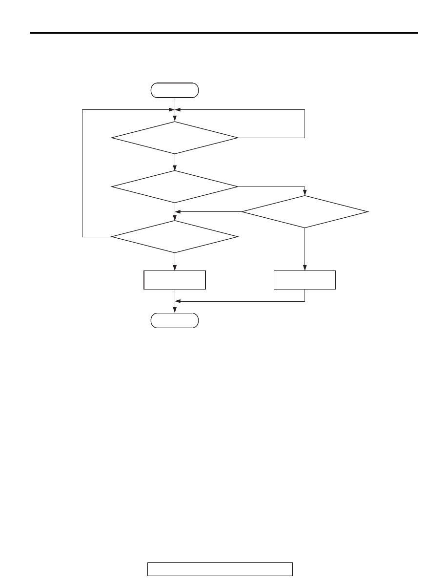
Logic Flow Chart
.
Check Conditions
• Battery positive voltage is between 11 and 16.5
volts.
• 2 seconds or more have passed since the engine
staring sequence was completed.
Judgement Criterion
• Fuel level sensor resistance has continued to be
2 ohms or lower for 2 seconds.
.
FAIL-SAFE AND BACKUP FUNCTION
• None
.
OBD-II DRIVE CYCLE PATTERN
Refer to Diagnostic Function − OBD-II Drive Cycle −
.
.
TROUBLESHOOTING HINTS (The most
likely causes for this code to be set are:)
• Fuel level sensor failed.
• Combination meters assembly failed.
• Connector damage
• Harness damage
• ECM failed.
DIAGNOSIS
Required Special Tools:
• MB991958: Scan Tool (M.U.T.-III Sub Assembly)
• MB991824: V.C.I.
• MB991827: USB Cable
• MB991910: Main Harness A
AK604342
Good
Malfunction
End
No
No
No
No
Fuel level sensor
resistance <= 2 ohms
Fuel level sensor
resistance >= 186 ohms
Start
Continuous
failure for 2secs
Monitoring
conditions
Yes
Yes
Yes
Yes