Mitsubishi Lancer Evolution X. Manual - part 322
MULTIPORT FUEL INJECTION (MFI) DIAGNOSIS
TSB Revision
MULTIPORT FUEL INJECTION (MFI)
13A-353
.
CIRCUIT OPERATION
• The turbocharger wastegate solenoid 1 power is
supplied from the MFI relay (terminal No. 2).
• The ECM controls ground the turbocharger
wastegate solenoid 1 by turning the power tran-
sistor in the ECM "ON" and "OFF".
.
TECHNICAL DESCRIPTION
• To judge if there is open circuit in the turbo-
charger wastegate solenoid 1 drive circuit, the
ECM measures the surge voltage of the turbo-
charger wastegate solenoid 1 coil.
• The ECM drives the turbocharger wastegate
solenoid 1. After the solenoid is turned off, the
ECM will check if the solenoid coil produces a
surge voltage of 2 volts or more.
.
DESCRIPTIONS OF MONITOR METHODS
If a surge current is not generated in the coil after the
turbocharger wastegate solenoid 1 has been
actuated, an open circuit is determined to have
occurred.
.
MONITOR EXECUTION
Continuous
.
MONITOR EXECUTION CONDITIONS
(Other monitor and Sensor)
Other Monitor (There is no temporary DTC stored
in memory for the item monitored below)
• Not applicable
Sensor (The sensor below is determined to be
normal)
• Not applicable
.
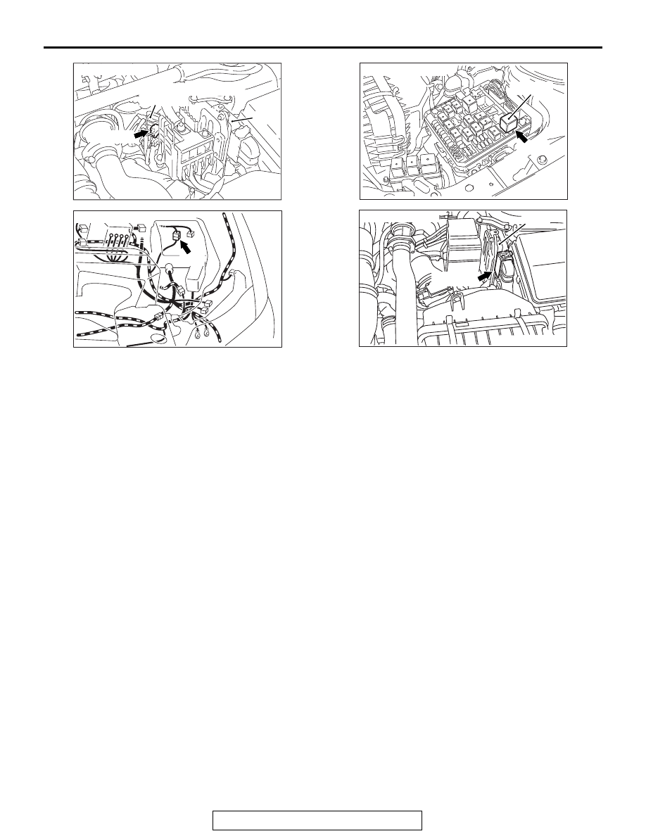
AK704406AB
Connector: A-10
A-10 (BR)
ECM
Turbocharger wastegate
solenoid 1
AK704229AB
Connector: A-13
A-13
AK704226
Connector: A-34X
MFI relay
A-34X
AB
AK704227
Connector: B-09
ECM
B-09 (GR)
AB