Mitsubishi Lancer Evolution X. Manual - part 310


  Index      Mitsubishi     Mitsubishi Lancer Evolution X GS41EVO - service repair manual 2008 year


Search            


Content   ..  308  309  310  311   ..


Mitsubishi Lancer Evolution X. Manual - part 310


MULTIPORT FUEL INJECTION (MFI) DIAGNOSIS

TSB Revision

MULTIPORT FUEL INJECTION (MFI)

13A-305

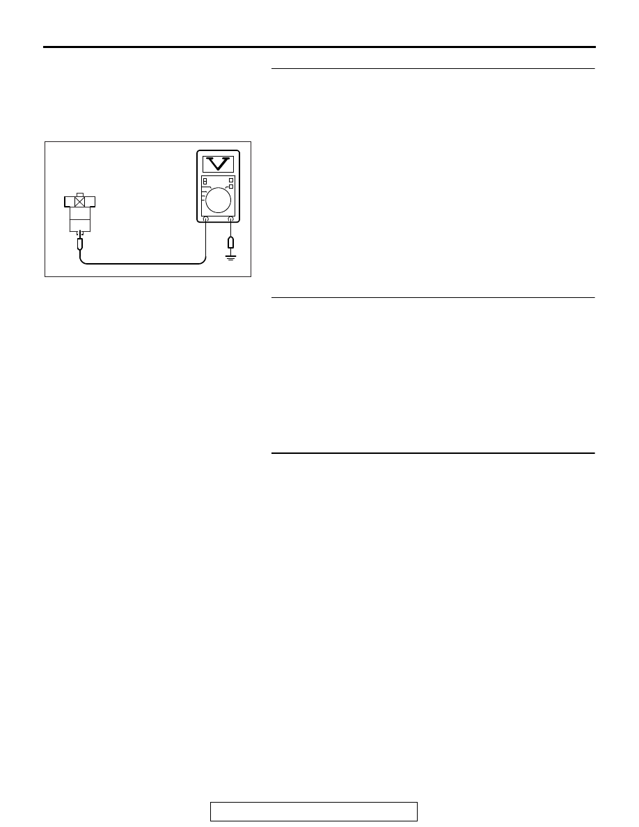
STEP 10. Measure the power supply voltage at injector 
relay harness side connector A-25X.
(1) Disconnect the connector A-25X and measure at the 

harness side.

(2) Turn the ignition switch to the "ON" position.
(3) Measure the voltage between terminal No. 4 and ground.

• Voltage should be battery positive voltage.

Q: Is battery positive voltage (approximately 12 volts) 

present?
YES : 
Go to Step 12.
NO :  Go to Step 11.

STEP 11. Check harness connector A-34X at MFI relay for 
damage.
Q: Is the harness connector in good condition?

YES : Repair harness wire between MFI relay connector 

A-34X (terminal No. 2) and injector relay 
connector A-25X (terminal No. 4) because of open 
circuit or short circuit to ground. Then go to Step 
20.

NO :  Repair or replace it. Refer to GROUP 00E, Harness 

Connector Inspection 

P.00E-2

. Then go to Step 20.

STEP 12. Check for open circuit or short circuit to ground 
between injector relay connector A-25X (terminal No. 3) 
and No. 1 cylinder injector connector B-101 (terminal No. 
1).
NOTE: Check harness after checking intermediate connector 
A-39. If intermediate connector is damaged, repair or replace it. 
Refer to GROUP 00E, Harness Connector Inspection 

P.00E-2

Then go to Step 20 .
Q: Is the harness wire in good condition?

YES : Go to Step 13.
NO :  Repair it. Then go to Step 20.

2

1

3
4

AK604035 AD

A-25X harness
connector:
component side

MULTIPORT FUEL INJECTION (MFI) DIAGNOSIS

TSB Revision

MULTIPORT FUEL INJECTION (MFI)

13A-306

STEP 13. Check harness connector C-304 at ETACS-ECU 
for damage.
Q: Is the harness connector in good condition?

YES : Check harness connector C-50 at intermediate 

connector for damage, and repair or replace as 
required. Refer to GROUP 00E, Harness Connector 
Inspectio

P.00E-2

. If intermediate connector is in 

good condition, repair harness wire between injector 
relay connector A-25X (terminal No. 1) and 
ETACS-ECU connector C-304 (terminal No. 10) 
because of harness damage. Then go to Step 20.

NO :  Repair or replace it. Refer to GROUP 00E, Harness 

Connector Inspection 

P.00E-2

. Then go to Step 20.

STEP 14. Check harness connector A-34X at MFI relay for 
damage.
Q: Is the harness connector in good condition?

YES : Go to Step 15.
NO :  Repair or replace it. Refer to GROUP 00E, Harness 

Connector Inspection 

P.00E-2

. Then go to Step 20.

STEP 15. Check for harness damage between MFI relay 
connector A-34X (terminal No. 2) and injector relay 
connector A-25X (terminal No. 4).
Q: Is the harness wire in good condition?

YES : Go to Step 16.
NO :  Repair it. Then go to Step 20.

STEP 16. Check for harness damage between injector 
relay connector A-25X (terminal No. 3) and No. 1 cylinder 
injector connector B-101 (terminal No. 1).
NOTE: Check harness after checking intermediate connector 
A-39. If intermediate connector is damaged, repair or replace it. 
Refer to GROUP 00E, Harness Connector Inspection 

P.00E-2

Then go to Step 20 .
Q: Is the harness wire in good condition?

YES : Go to Step 17.
NO :  Repair it. Then go to Step 20.

STEP 17. Check harness connector B-09 at ECM for 
damage.
Q: Is the harness connector in good condition?

YES : Go to Step 18.
NO :  Repair or replace it. Refer to GROUP 00E, Harness 

Connector Inspection 

P.00E-2

. Then go to Step 20.

MULTIPORT FUEL INJECTION (MFI) DIAGNOSIS

TSB Revision

MULTIPORT FUEL INJECTION (MFI)

13A-307

STEP 18. Check for open circuit and short circuit to 
ground and harness damage between No. 1 cylinder 
injector connector B-101 (terminal No. 2) and ECM 
connector B-09 (terminal No. 2).
Q: Is the harness wire in good condition?

YES : Go to Step 19.
NO :  Repair it. Then go to Step 20.

STEP 19. Using the oscilloscope, check the No. 1 cylinder 
injector.
(1) Disconnect the No. 1 cylinder injector connector B-101 and 

connect the test harness special tool MB991658 between 
the separated connectors. (All terminals should be 
connected.)

(2) Connect the oscilloscope probe to the injector side 

connector terminal No. 2.
NOTE: When measuring with the ECM side connector, dis-
connect all ECM connectors. Connect the check harness 
special tool (MB992110) between the separated connec-
tors. Then connect the oscilloscope probe to the check har-
ness connector terminal No. 2.

(3) Start the engine and run at idle.

(4) Measure the waveform.

• The waveform should show a normal pattern similar to 

the illustration.

(5) Turn the ignition switch to the "LOCK" (OFF) position.
Q: Is the waveform normal?

YES : It can be assumed that this malfunction is intermittent. 

Refer to GROUP 00, How to Use 
Troubleshooting/Inspection Service Points − How to 

Cope with Intermittent Malfunctions 

P.00-15

.

NO :  Replace the ECM. When the ECM is replaced, 

register the ID code. Refer to GROUP 42B, ID Code 
Registration Necessity Judgment Table <Vehicles 
with KOS> 

P.42B-11

 or GROUP 42C, ID Codes 

Registration Judgment Table <Vehicles with WCM> 

P.42C-9

. Then go to Step 20.

STEP 20. Test the OBD-II drive cycle.
(1) Carry out a test drive with the drive cycle pattern. Refer to 

Diagnostic Function − OBD-II Drive Cycle − Pattern 23 

P.13A-9

.

(2) Check the diagnostic trouble code (DTC). 
Q: Is DTC P0201 set?

YES : Retry the troubleshooting.
NO :  The inspection is complete.

AK604471

1 2

AB

Injector
connector

MB991658

Oscilloscope

AK604546 AB

A

Normal  waveform

A:Injector drivetime 

MULTIPORT FUEL INJECTION (MFI) DIAGNOSIS

TSB Revision

MULTIPORT FUEL INJECTION (MFI)

13A-308

DTC P0202: Injector Circuit-Cylinder 2

AK704261

1

3

2

4

1

2

3
4

1

2

3 4 5 6 7 8 9 10 11 12 13 14 15 16

17 18 19 20 21 22 23 24 25 26 27 28 29 30 31 32

33 34 35 36 37 38 39 40 41 42 43 44 45 46 47 48

49 50 51 52 53 54 55 56 57 58 59 60 61 62 63 64

1 2 3 4

5 6 7

15

14

13

12

11

9

8

10

1

6

4

5

9

8

10 11

13

15

14

12

16

7

2 3

2

1

1 2 3

4 5 6

1

12 13 14 15 16 1718 19 20 2122 2324

2 3 4 5

6 7 8 9 10 11

INJECTOR
NO. 2

B-102

(MU802062)

A-39

MU802607

1

2

3

INJECTOR CIRCUIT-CYLINDER 2

RED-BLA

CK

RED-

BLA

CK

YELLO

W

-BLA

CK

B-09

AC

20A

WHITE

WHITE

A-34X

MFI
RELAY

4

3

1

2

22

36

FUSIBLE LINK

OFF

ON

WHITE

WHITE

RED-

GREEN

RED-

GREEN

4

1

14

10

15

6

7

C-304

C-317

J-C (7)

C-50

A-21X

3

2

IGNITION
SWITCH (IG1)

ETACS-
ECU

INJECTOR
RELAY

OFF

ON

RELAY BOX
(ENGINE COMPARTMENT)

ENGINE CONTROL MODULE

TO ECM

BLA

CK

BLA

CK

BLA

CK

BLA

CK


Content   ..  308  309  310  311   ..