Mitsubishi Lancer Evolution X. Manual - part 276
MULTIPORT FUEL INJECTION (MFI) DIAGNOSIS
TSB Revision
MULTIPORT FUEL INJECTION (MFI)
13A-169
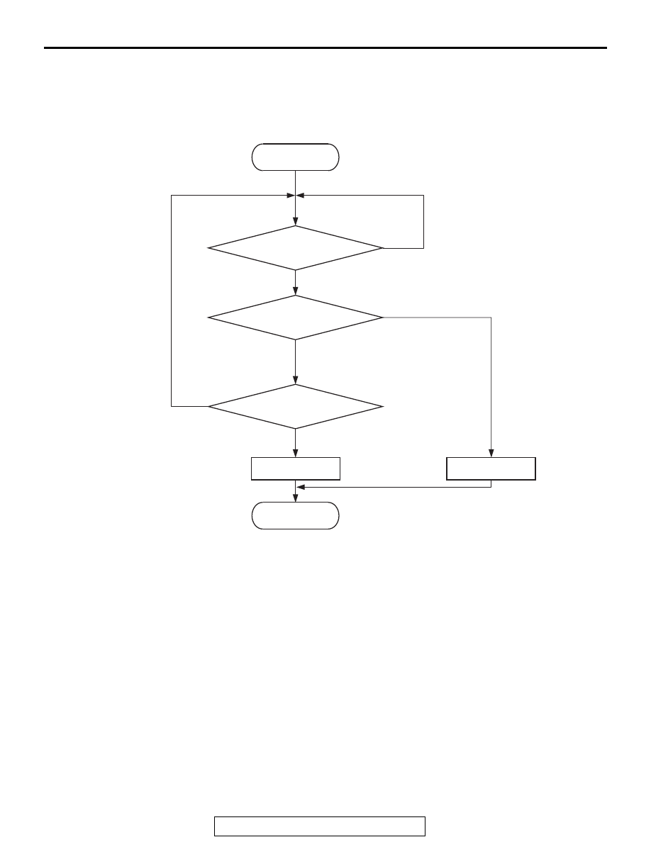
DTC SET CONDITIONS
Logic Flow Chart
.
Check Conditions
• Engine coolant temperature is higher than 76° C
(169° F).
• Repeat 2 or more times: drive
*1
, stop
*2
.
Drive
*1
: vehicle speed higher than 50 km/h (31
mph) lasting a total of 60 seconds or more.
Stop
*2
: vehicle speed lower than 1.5 km/h (1.0
mph) lasting 30 seconds or more.
Judgement Criterion
• Changes in the intake air temperature is lower
than 1° C (1.8° F).
.
FAIL-SAFE AND BACKUP FUNCTION
• Control as if the intake air temperature is 25 ° C.
.
OBD-II DRIVE CYCLE PATTERN
Refer to Diagnostic Function − OBD-II Drive Cycle −
Pattern 7
.
.
TROUBLESHOOTING HINTS (The most
likely causes for this code to be set are:)
• Intake air temperature sensor 1 failed.
• Harness damage or connector damage.
• ECM failed.
End
Malfunction
Yes
Yes
No
No
Yes
No
Go/stop operation
for specified times
Intake air temp.
changes
Monitoring
conditions
Good
Start
AK604314