Mitsubishi Lancer Evolution X. Manual - part 209


  Index      Mitsubishi     Mitsubishi Lancer Evolution X GS41EVO - service repair manual 2008 year


Search            


Content   ..  207  208  209  210   ..


Mitsubishi Lancer Evolution X. Manual - part 209


WHEEL SPEED SENSOR

TSB Revision

ACTIVE STABILITY CONTROL SYSTEM (ASC)

35C-301

NOTE: The vehicle speed detection encoder is inte-
grated with the front wheel bearing and the rear hub 
assembly, which cannot be disassembled.

INSTALLATION SERVICE POINTS

.

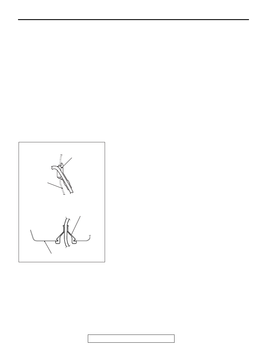
>>A<< FRONT WHEEL SPEED SENSOR GROM-
MET/REAR WHEEL SPEED SENSOR GROMMET 
INSTALLATION

Install the front wheel speed sensor grommet and the rear 
wheel speed sensor grommet to the body panel snugly as 
shown in the figure.

.

Front wheel speed sensor 
removal steps 

>>

C

<<

1. Front wheel speed sensor 

connector

>>

A

<<

2. Front wheel speed sensor 

grommet

3. Bolt (front wheel speed sensor 

and knuckle connection)

>>

B

<<

4. Sensor harness clip
5. Front wheel speed sensor

Rear wheel speed sensor 
removal steps 

Trunk room front trim (Refer to 
GROUP 52A − Trim 

P.52A-12

.)

6. Rear wheel speed sensor 

connector

>>

A

<<

7. Rear wheel speed sensor 

grommet

8. Bolt (rear wheel speed sensor 

and knuckle assembly 
connection)

9. Rear wheel speed sensor

AC710757AB

Front wheel speed
sensor grommet

Body panel

<Front>

<Rear>

Rear wheel speed
sensor grommet

Body panel

WHEEL SPEED SENSOR

TSB Revision

ACTIVE STABILITY CONTROL SYSTEM (ASC)

35C-302

>>B<< SENSOR HARNESS CLIP INSTALLATION

As shown in the figure, align the edge of front wheel speed sen-
sor marking with the edge of sensor wiring harness clip, then 
perform the installation.

.

>>C<< FRONT WHEEL SPEED SENSOR 
CONNECTOR INSTALLATION

As shown in the figure, align the edge of front wheel speed sen-
sor marking with the edge of clip, then perform the installation.

AC706886

Marking

Sensor harness clip

Sensor harness clip

Front
wheel
speed
sensor

<Section A - A>

AC706886

A

A

Strut assembly

B

B

AB

<Section B - B>

Front wheel speed sensor

AC710758AB

Front wheel speed
sensor <LH>

Clip

Marking

Hydraulic unit
(integrated with
ASC-ECU)

WHEEL SPEED SENSOR

TSB Revision

ACTIVE STABILITY CONTROL SYSTEM (ASC)

35C-303

INSPECTION

M1352008400880

.

WHEEL SPEED SENSOR CURRENT CHECK

CAUTION

Do not connect the battery terminals in reverse as the 
wheel speed sensor may be damaged.
1. Connect the circuit tester to the wheel speed sensor using 

the special tool extra fine probe (MB992006), and measure 
the sensor current as a single unit.
NOTE: 

.

When measuring at the front wheel speed sensor

Do not remove the front wheel speed sensor from the 
knuckle.

.

When measuring at the rear wheel speed sensor

Do not remove the rear wheel speed sensor from the 
knuckle.

Standard value: 5.9 to 8.4 mA or 11.8 to 16.8 mA

2. If the measurement value is not within the standard value 

range, replace the wheel speed sensor with a new one.

.

WHEEL SPEED SENSOR INSULATION CHECK

1. Connect the circuit tester to the wheel speed sensor using 

the special tool extra fine probe (MB992006), and measure 
the insulation resistance between terminal No. 1/2 and the 
wheel speed sensor body as a single unit.

Standard value: 5 MΩ or more

2. If the insulation resistance is not within the standard value 

range, replace the wheel speed sensor with a new one.

AC608846

MB992006

AB

AC608847

MB992006

<Front>

<Rear>

AB

G AND YAW RATE SENSOR

TSB Revision

ACTIVE STABILITY CONTROL SYSTEM (ASC)

35C-304

G AND YAW RATE SENSOR

REMOVAL AND INSTALLATION

M1355004500204

CAUTION

• Do not use an impact wrench.
• Do not drop or shock the G and yaw rate sensor.
• When the G and yaw rate sensor is replaced, always carry out calibration to make ASC-ECU learn 

the neutral point. (Refer to 

P.35C-287

.)

Pre-removal and post-installation steps
Floor console side cover removal and installation (Refer to 
GROUP 52A − Floor Console Assembly 

P.52A-10

.)

AC613540AB

1

2

4

5

10 ± 2 N·m
89 ± 17 in-lb

3

5.0 ± 1.0 N·m
44 ± 9 in-lb

Removal steps 

1. Front O

2

 sensor connector

2. G and yaw rate sensor connector

3. G and yaw rate sensor and G and 

yaw rate sensor bracket

4. G and yaw rate sensor
5. G and yaw rate sensor bracket

Removal steps (Continued)


Content   ..  207  208  209  210   ..