Mitsubishi Lancer Evolution X. Manual - part 129


  Index      Mitsubishi     Mitsubishi Lancer Evolution X GS41EVO - service repair manual 2008 year


Search            


Content   ..  127  128  129  130   ..


Mitsubishi Lancer Evolution X. Manual - part 129


ON-VEHICLE SERVICE

TSB Revision

BASIC BRAKE SYSTEM

35A-21

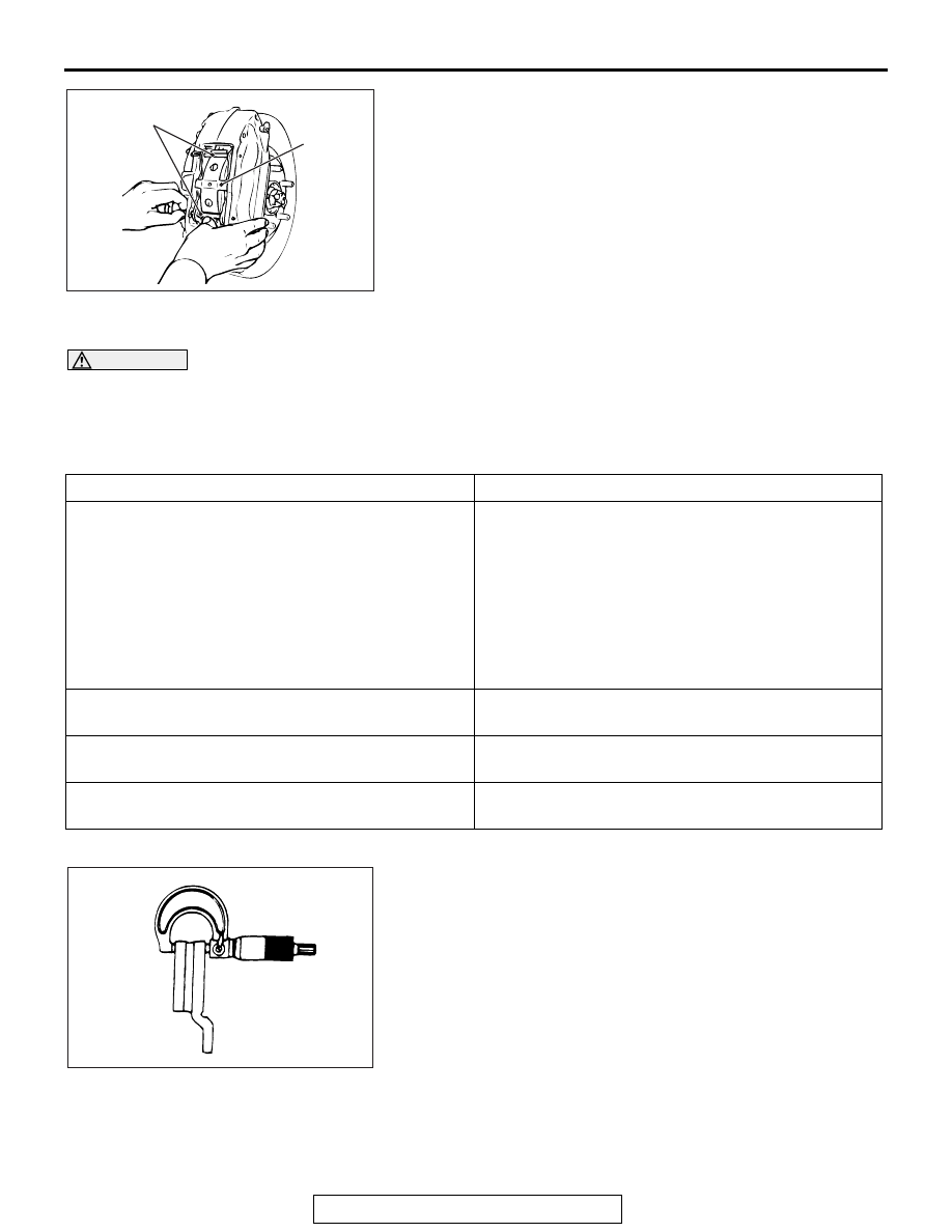
8. While pressing the cross spring by hand, install the pin to 

the brake caliper assembly.

DISK BRAKE ROTOR CHECK

M1351002900710

CAUTION

Disk brakes must be kept within the allowable 
service values in order to maintain normal brake 
operation.
Before turning the brake disk, the following condi-
tions should be checked.

.

BRAKE DISK THICKNESS CHECK

1. Using a micrometer, measure disk thickness at eight 

positions, approximately 45 degrees apart and 10 mm (0.4 
inch) in from the outer edge of the disk.

Standard value:

32.0 mm (1.26 inch) <Front>
22.0 mm (0.87 inch) <Rear>

Limit:

30.0 mm (1.18 inch) <Front>
20.0 mm (0.79 inch) <Rear>

NOTE: Thickness variation (at least 8 positions) should not 
be more than 0.015 mm (0.0006 inch).

AC211990AC

Cross 
spring

Pin

Inspection item

Remark

Scratches, rust, saturated lining materials and wear

• If the vehicle is not driven for a long period of 

time, sections of the disks that are not in contact 
with the pads will become rusty, causing noise 
and shuddering.

• If grooves and scratches resulting from excessive 

disk wear are not removed prior to installing a new 
pad assembly, there will be inadequate contact 
between the disk and the lining (pad) until the 
pads conform to the disk.

Run-out

Excessive run-out of the disks will increase the pedal 
depression resistance due to piston kick-back.

Change in thickness (parallelism)

If the thickness of the disk changes, this will cause 
pedal pulsation, shuddering and surging.

Inset or warping (flatness)

Overheating and improper handling while servicing 
will cause warping or distortion.

ACX00668AB

ON-VEHICLE SERVICE

TSB Revision

BASIC BRAKE SYSTEM

35A-22

CAUTION

• After a new brake disk is installed, always grind the 

brake disk with on-the-car type brake lathe. If this step 
is not carried out, the brake disk run-out exceeds the 
specified value, resulting in judder.

• When the on-the-car type lathe is used, first install M12 

flat washer on the stud bolt in the brake disk side 
according to the figure, and then install the adapter. If 
the adapter is installed with M12 flat washer not seated, 
the brake disk rotor may be deformed, resulting in inac-
curate grinding.

• Grind the brake disk with all wheel nuts diagonally and 

equally tightened to the specified torque 100 N⋅ m (74 

ft-lb). When all numbers of wheel nuts are not used, or 
the tightening torque is excessive or not equal, the 
brake disk rotor or drum may be deformed, resulting in 
judder.

2. If the disk thickness is less than the limits, replace it with a 

new one. If thickness variation exceeds the specification, 
turn rotor with an on-the-car type brake lathe ("MAD, 
DL-8700PF" or equivalent). If the calculated final thickness 
after turning the rotor is less than the standard value, 
replace the disk.

.

FRONT BRAKE DISK RUN-OUT CHECK AND 
CORRECTION

1. Remove the brake assembly, and then hold it with wire.
2. Temporarily install the disk with the hub nut.
3. Place a dial gauge approximately 5 mm (0.2 inch) from the 

outer circumference of the brake disk, and measure the 
run-out of the disk.

Limit:

0.06 mm (0.0024 inch) <Front>
0.08 mm (0.0032 inch) <Rear>

4. When the brake disk run-out exceeds the limit value, correct 

the brake disk run-out according to the following procedure.

AC006226 AE

M12 Flat washer

M12 Flat washer

ACX00669AB

ON-VEHICLE SERVICE

TSB Revision

BASIC BRAKE SYSTEM

35A-23

(1) Before removing the brake disk, make marks using a 

chalk to the stud bolt on the side with the greater run-out 
and to both sides of the stud bolt.

(2) Check the wheel bearing axial looseness. (Refer to 

GROUP 26 − On-vehicle Service, Wheel Bearing End 

Play Check 

P.26-7

 <Front> or GROUP 27 − On-vehicle 

Service, Wheel Bearing End Play Check 

P.27-32


<Rear>.)

(3) When the looseness is within the limit value, install the 

brake disk after changing the phase between the hub and 
the brake disk, then check the run-out of the brake disk 
again.

CAUTION

• After a new brake disk is installed, always grind the 

brake disk with on-the-car type brake lathe. If this step 
is not carried out, the brake disk run-out exceeds the 
specified value, resulting in judder.

• When the on-the-car type lathe is used, first install M12 

flat washer on the stud bolt in the brake disk side 
according to the figure, and then install the adapter. If 
the adapter is installed with M12 flat washer not seated, 
the brake disk rotor may be deformed, resulting in inac-
curate grinding.

• Grind the brake disk with all wheel nuts diagonally and 

equally tightened to the specified torque 100 N⋅ m (74 

ft-lb). When all numbers of wheel nuts are not used, or 
the tightening torque is excessive or not equal, the 
brake disk rotor or drum may be deformed, resulting in 
judder.

5. If the run-out cannot be corrected by changing the phase of 

the brake disk, replace the brake disk or grind it with the 
on-the-car type brake lathe ("MAD, DL-8700PF" or 
equivalent).

BRAKE DRAG FORCE CHECK

M1351017200052

1. Remove the brake pad, shim, and clip. (Refer to 

P.35A-18

.)

2. Using a spring scale, and with the brake pad, shim, and clip 

removed, measure the hub sliding torque in the forward 
direction.

3. Install the brake pad, shim, and clip. (Refer to 

P.35A-18

.)

4. Start the engine, and depress the brake pedal forcibly two or 

three times. Then, stop the engine.

5. Rotate the brake disk 10 times in the forward direction.
6. Using a spring scale, and with the brake pad, shim, and clip 

installed, measure the hub sliding torque in the forward 
direction.

AC201323 AD

Chalk marks

AC006226 AE

M12 Flat washer

M12 Flat washer

AC707502AB

Front of vehicle

BRAKE PEDAL

TSB Revision

BASIC BRAKE SYSTEM

35A-24

7. Obtain the disk brake drag force (difference between 

measured values of Step 2 and Step 6).

Standard value: 68 N (15.3 pounds) or less

8. If the brake drag force exceeds the standard value, 

disassemble the brake caliper assembly, and check the 
fouling/rust on the piston sliding section, piston seal 
deterioration, and the sliding status of guide pin and lock pin. 
(Refer to 

P.35A-32

 <Front> or 

P.35A-37

 <Rear>.)

BRAKE PEDAL

REMOVAL AND INSTALLATION

M1351003401131

CAUTION

Do not apply grease or lubricant to the switch and the switch installation section to avoid malfunction 
of the switch. In addition, do not use gloves which have grease on them.

Pre-removal operation
Instrument panel cover lower removal (Refer to GROUP 52A 
− Instrument Lower Panel 

P.52A-9

) <MR>.

Post-installation operation
Instrument panel cover lower installation (Refer to GROUP 
52A − Instrument Lower Panel 

P.52A-9

) <MR>.

AC709280AB

3

2

6

7

1

7

5

8

4

<M/T>

<TC-SST>

14 ± 3 N·m
124 ± 26 in-lb

15 ± 3 N·m
11 ± 2 ft-lb


Content   ..  127  128  129  130   ..