Mitsubishi Lancer Evolution X. Manual - part 121


  Index      Mitsubishi     Mitsubishi Lancer Evolution X GS41EVO - service repair manual 2008 year


Search            


Content   ..  119  120  121  122   ..


Mitsubishi Lancer Evolution X. Manual - part 121


EMISSION CONTROL <MFI - T/C>

TSB Revision

ENGINE AND EMISSION CONTROL

17-71

VACUUM HOSE INSTALLATION

M1173007200486

1. When connecting the vacuum hoses, they should be 

securely inserted onto the nipples.

2. Connect the hoses correctly, using the VACUUM HOSE 

ROUTING diagram as a guide.

VACUUM HOSE CHECK

M1173007300762

1. Using the VACUUM HOSE ROUTING diagram as a guide, 

check that the vacuum hoses are correctly connected.

2. Check the connection condition of the vacuum hoses which 

can be removed, loosened, clogged possibly. And then 
check whether there are no folded and damaged vacuum 
hoses.

POSITIVE CRANKCASE VENTILATION SYSTEM

GENERAL INFORMATION (POSITIVE CRANKCASE VENTILATION SYSTEM)

M1173005001199

The positive crankcase ventilation (PCV) system pre-
vents the escape of blow-by gases from inside the 
crankcase into the atmosphere.
Fresh air is sent from the air cleaner into the crank-
case through the breather hose to be mixed with the 
blow-by gas inside the crankcase.
The blow-by gas inside the crankcase is drawn into 
the intake manifold through the PCV valve.

The PCV valve is designed to lift the plunger accord-
ing to the intake manifold vacuum so as to regulate 
the flow of blow-by gas properly.
In other words, the blow-by gas flow is regulated dur-
ing low load engine operation to maintain engine sta-
bility, while the flow is increased during high load 
operation to improve the ventilation performance.
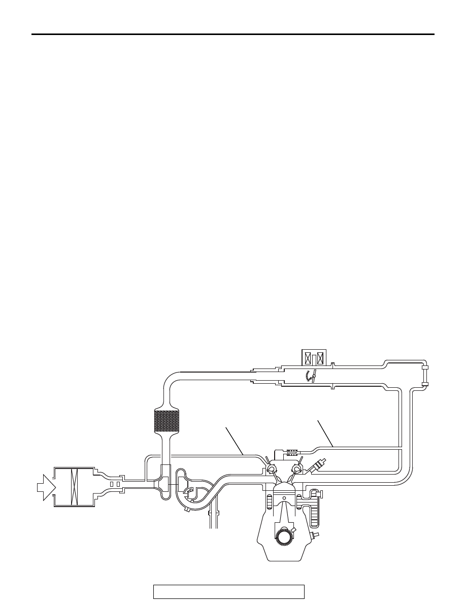
SYSTEM DIAGRAM

AK703398 AD

Air cleaner

Positive crankcase
ventilation valve

Ventilation hose

Breather hose

EMISSION CONTROL <MFI - T/C>

TSB Revision

ENGINE AND EMISSION CONTROL

17-72

COMPONENT LOCATION

M1173007400833

CRANKCASE VENTILATION SYSTEM CHECK

M1173001100878

1. Remove the ventilation hose from the positive crankcase 

ventilation (PCV) valve.

2. Remove the PCV valve from the rocker cover.
3. Reinstall the PCV valve at the ventilation hose.
4. Start the engine and run at idle.
5. Place a finger at the opening of the PCV valve and check 

that vacuum of the intake manifold is felt.
NOTE: At this moment, the plunger in the PCV valve moves 
back and forth.

6. If vacuum is not felt, clean the PCV valve or replace it.
7. Apply a small amount of new engine oil to the O-ring on the 

PCV valve, and tighten to the specified torque. 

Standard value: 2.5 ± 0.4 N⋅ m (22 ± 3 in-lb)

POSITIVE CRANKCASE VENTILATION (PCV) 
VALVE CHECK

M1173001200808

1. Remove the ventilation hose from the positive crankcase 

ventilation (PCV) valve.

2. Remove the PCV valve from the rocker cover.
3. Hold the PCV valve with the vacuum side down. Insert a thin 

rod, and using light pressure, depress the end of the PCV 
valve spring by 5 − 10 mm (0.2 − 0.3 inch). Release pressure 

on the rod to see if the PCV valve spring will lift the rod to its 
original position.

4. If the rod returns quickly to its original position, the PCV 

valve is OK. If the stick does not return quickly, clean or 
replace the PCV valve.

5. Apply a small amount of new engine oil to the O-ring on the 

PCV valve, and tighten to the specified torque. 

Standard value: 2.5 ± 0.4 N⋅ m (22 ± 3 in-lb)

AK703198AD

Positive crankcase
ventilation valve

AK604163

Positive crankcase 
ventilation valve

AB

AK604164

Positive crankcase 
ventilation valve

Thin rod 
(very smooth)

5 10 mm

(0.2 0.3 in)

Vacuum side

AB

EMISSION CONTROL <MFI - T/C>

TSB Revision

ENGINE AND EMISSION CONTROL

17-73

EVAPORATIVE EMISSION CONTROL SYSTEM

GENERAL INFORMATION (EVAPORATIVE EMISSION SYSTEM)

M1173005101732

The evaporative emission (EVAP) system prevents 
fuel vapors generated in the fuel tank from escaping 
into the atmosphere.
Fuel vapors from the fuel tank flow through the vapor 
pipe/hose to be stored temporarily in the EVAP can-
ister.
When the vehicle is in operation, fuel vapors stored 
in the EVAP canister flow through the EVAP purge 
solenoid, purge port and intake manifold plenum to 
the combustion chamber.
When the engine coolant temperature is low or when 
the intake air quantity is small (when the engine is at 
idle, for example), the engine control module (ECM) 
brings the EVAP purge solenoid into the OFF state to 
shut off the fuel vapor flow to the intake manifold ple-
num. This ensures driveability when the engine is 
cold or running under low load and also stabilizes the 
emission level.

An EVAP ventilation solenoid is provided between 
the EVAP canister and atmosphere to monitor for 
OBD-II EVAP leaks. This solenoid is normally OFF. 
However, it turns ON when monitoring for OBD-II 
EVAP leaks and shuts off the atmosphere flow to the 
EVAP canister. Then the fuel tank differential pres-
sure sensor monitors the fuel vapor pressure to 
detect OBD-II EVAP leaks.
When the fuel tank inner pressure increases due to 
the fuel supply, air is released to the atmosphere 
from the fuel tank through the EVAP canister and air 
filter. When the inner pressure of the fuel tank 
decreases, air is supplied to the fuel tank through the 
air filter and EVAP canister.

EMISSION CONTROL <MFI - T/C>

TSB Revision

ENGINE AND EMISSION CONTROL

17-74

SYSTEM DIAGRAM

AK900301

Evaporative emission
purge solenoid

Battery

Check valve

ECM

Mass airflow sensor

Throttle position sensor

Intake air
temperature sensor 1

Barometric
pressure sensor

Engine coolant
temperature sensor

Crankshaft position
sensor

AB

Evaporative emission 
ventilation solenoid 

Air filter

Fuel tank differential 
pressure sensor

Liquid separator

Evaporative
emission canister

Fuel tank

Leveling
valve


Content   ..  119  120  121  122   ..