Mitsubishi Lancer Evolution X. Manual - part 102


  Index      Mitsubishi     Mitsubishi Lancer Evolution X GS41EVO - service repair manual 2008 year


Search            


Content   ..  100  101  102  103   ..


Mitsubishi Lancer Evolution X. Manual - part 102


IGNITION SYSTEM

TSB Revision

ENGINE ELECTRICAL

16-39

SPARK PLUG CLEANING

NOTE: Using a sand blast type plug cleaner, is recommended 
for the spark plug cleaning.

.

<When a sand blast type plug cleaner is used>

Cleaning must be carried out within 20 seconds to protect the 
electrode.

.

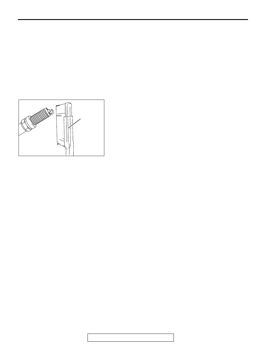
<When special tool MB992273 is used>

1. Sufficiently apply the brake cleaner to the plug end.

NOTE: Repeatedly applying the brake cleaner is acceptable 
during the cleaning.

2. Using special tool MB992273, intensively clean the 

electrode for 1 to 2 minutes.
NOTE: Even if using strong force, the electrode is not dam-
aged.
NOTE: In case of insufficient cleaning, it is permissible to 
take longer than 2 minutes for cleaning.

3. After the cleaning, sufficiently remove and then dry both of 

the carbon and the brake cleaner on the plug, using a waste 
cloth or air blowing.

CAMSHAFT POSITION SENSOR CHECK

M1163004400792

Refer to GROUP 13A, Multiport Fuel Injection (MFI) − Multiport 

Fuel Injection (MFI) Diagnosis − Diagnostic Trouble Code Pro-

cedures − DTC P0340: Intake Camshaft Position Sensor Circuit 

P.13A-399

.

CRANKSHAFT POSITION SENSOR CHECK

M1163004500841

Refer to GROUP 13A, Multiport Fuel Injection (MFI) − Multiport 

Fuel Injection (MFI) Diagnosis − Diagnostic Trouble Code Pro-

cedures − DTC P0335: Crankshaft Position Sensor Circuit 

P.13A-389

.

AK705045

MB992273

AD

IGNITION SYSTEM

TSB Revision

ENGINE ELECTRICAL

16-40

IGNITION COIL

REMOVAL AND INSTALLATION

M1163004001980

AC506572

AC704355

AC706231AD

1

2

4

3

9.5 ± 2.5 N·m
84 ± 22 in-lb

18 ± 2 N·m
13 ± 1 ft-lb

Removal steps 

1.

Engine upper cover

2.

Ignition coil connector connection

3.

Ignition coil

4.

Spark plug

Removal steps (Continued)

IGNITION SYSTEM

TSB Revision

ENGINE ELECTRICAL

16-41

CAMSHAFT POSITION SENSOR

REMOVAL AND INSTALLATION

M1163003401349

AC709301AB

1

2

3

4

5

N

N

9.5 ± 2.5 N·m
84 ± 22 in-lb

28 ± 8 N·m
21 ± 6 ft-lb

(Engine oil)

9.5 ± 2.5 N·m
84 ± 22 in-lb

6

7

(Engine oil)

Exhaust camshaft position 
sensor removal steps 

1.

Engine hanger

2.

Exhaust camshaft position sensor 
connector connection

3.

Camshaft position sensor

4.

O-ring

Intake camshaft position 
sensor removal steps 

5.

Intake camshaft position sensor 
connector connection

6.

Camshaft position sensor

7.

O-ring

IGNITION SYSTEM

TSB Revision

ENGINE ELECTRICAL

16-42

CRANKSHAFT POSITION SENSOR

REMOVAL AND INSTALLATION

M1163003500860

Pre-removal and post-installation operation
• Engine Room Under Cover Front A, B and Engine Room 

Under Cover Center Removal and Installation (Refer to 

GROUP 51, Under Cover 

P.51-15

).

AC706620

1

2

AC

3

N

9.5 ± 2.5 N·m
84 ± 22 in-lb

(Engine oil)

Removal steps 

1.

Crankshaft position sensor 
connector connection

2.

Crankshaft position sensor

3.

O-ring

Removal steps (Continued)


Content   ..  100  101  102  103   ..