Mitsubishi Lancer Evolution X. Manual - part 79


  Index      Mitsubishi     Mitsubishi Lancer Evolution X GS41EVO - service repair manual 2008 year


Search            


Content   ..  77  78  79  80   ..


Mitsubishi Lancer Evolution X. Manual - part 79


TIMING CHAIN

TSB Revision

ENGINE MECHANICAL

11A-69

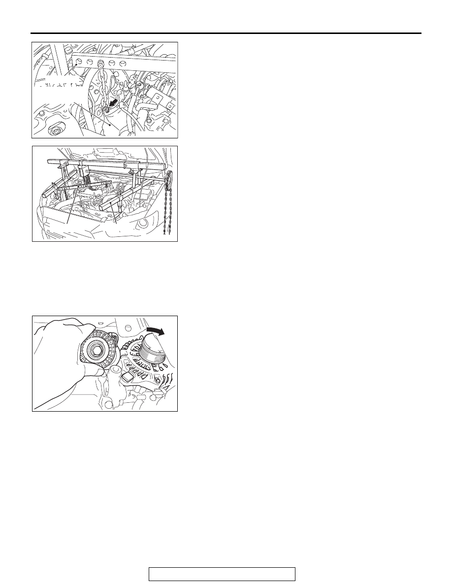
(2) Mount special tool MB991454 to the power steering oil 

pump bracket and the engine hanger, and set it to special 
tool MB991895 to support the engine and transaxle 
assembly.

.

<<C>> CRANKSHAFT PULLEY REMOVAL

When removing the crankshaft pulley, slightly loosen the water 
pump pulley mounting bolts before removal of the drive belt.

.

<<D>> AUTO-TENSIONER REMOVAL

Loosen the mounting bolt of generator assembly lower part, 
and remove the mounting bolt of generator assembly upper 
part. Slide the generator assembly, and remove the auto-ten-
sioner.

.

AC706145AC

MB991454

Power steering
oil pump bracket

AC705462

MB991454

AC

MB991895

AC705464AC

TIMING CHAIN

TSB Revision

ENGINE MECHANICAL

11A-70

<<E>> TIMING CHAIN CASE ASSEMBLY 
REMOVAL

CAUTION

If the adhesive strength of sealant on the timing chain case 
assembly is so strong that the boss may be damaged by 
peeling off, do not peel it off forcibly. 
1. After removing the timing chain case assembly mounting 

bolts, slightly pry the boss of the timing chain case assembly 
shown in the figure using a flat-tipped screwdriver, and 
remove the timing chain case assembly from the cylinder 
head and cylinder block.

2. If the sealant cannot be peeled off easily, insert a wooden 

hammer shank into the timing chain case assembly inside 
as shown in the figure, pry slightly, and remove the timing 
chain case assembly from the cylinder head and cylinder 
block.

.

<<F>> TIMING CHAIN TENSIONER REMOVAL

1. Temporarily install the crankshaft pulley to the crankshaft.

AC705463 AC

Boss

Timing chain
case assembly

AC506771

AC

Hammer

Timing chain
case assembly

TIMING CHAIN

TSB Revision

ENGINE MECHANICAL

11A-71

CAUTION

Turn the crankshaft clockwise.
2. Turn the crankshaft clockwise to align the sprocket timing 

marks as shown in the figure and set the cylinder No. 1 to 
the top dead center of compression stroke.
NOTE: At this time, it is not necessary that the link plate 
(blue) of the timing chain always aligns with each sprocket 
timing mark.

3. Remove the crankshaft pulley installed temporarily.

4. Using a flat-tipped precision screwdriver, release the ratchet 

of timing chain tensioner. 

5. Compress the plunger of timing chain tensioner and insert 

hard wire (such as piano wire) or the L-shaped hexagon 
wrench (1.5 mm[0.05 inch]) to fix the plunger of the timing 
chain tensioner.

6. Remove the timing chain tensioner.

AC506772

AG

Camshaft sprocket
timing marks

Crankshaft sprocket
timing mark

AC506773

AD

Timing chain 
tensioner

Ratchet release hole

Hard wire or 
L-shaped 
hexagon 
wrench

TIMING CHAIN

TSB Revision

ENGINE MECHANICAL

11A-72

INSTALLATION SERVICE POINTS

.

>>A<< TIMING CHAIN INSTALLATION

1. Set the timing marks of the camshaft sprockets and the 

crankshaft sprocket as shown in the figure.

2. Align each sprocket timing chain mating mark with the link 

plate (blue) of timing chain to avoid slack of the timing chain 
tension side, and install the timing chain to the sprockets.

.

AC710641

AB

Camshaft sprocket
timing marks

Crankshaft sprocket
timing mark

AC506772

AP

Tension side

Link plates (blue)

Link plate (blue)

Mating 
mark

Mating 
mark

Mating mark


Content   ..  77  78  79  80   ..