Mitsubishi Lancer Evolution X. Manual - part 77


  Index      Mitsubishi     Mitsubishi Lancer Evolution X GS41EVO - service repair manual 2008 year


Search            


Content   ..  75  76  77  78   ..


Mitsubishi Lancer Evolution X. Manual - part 77


CYLINDER HEAD GASKET

TSB Revision

ENGINE MECHANICAL

11A-61

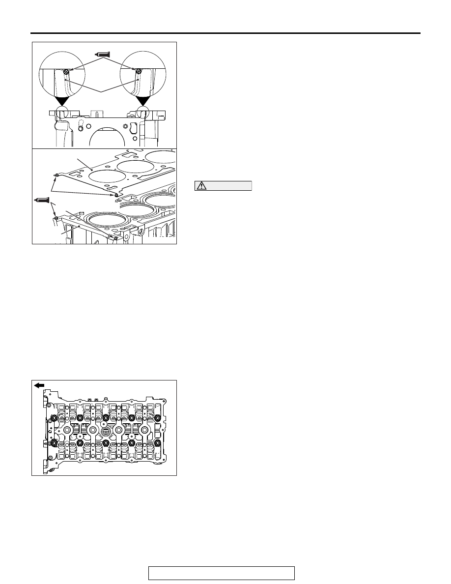
2. Apply the sealant to the top surface of cylinder block as 

shown in the figure.

Specified sealant: Three bond 1217G or equivalent

3. Install the cylinder head gasket to the cylinder block.

NOTE: 

.

Install the cylinder head gasket immediately after apply-
ing sealant.

When the cylinder gasket is installed to the cylinder 
block, check that the sealant is securely applied to the 
bead line of the cylinder head gasket.

4. Apply the sealant to the top surface of cylinder head gasket 

as shown in the figure.

Specified sealant: Three bond 1217G or equivalent

CAUTION

After the installation, until a sufficient period of time (one 
hour or more) elapses, do not apply the oil or water to the 
sealant application area or start the engine.
5. Within three minutes after the sealant application, install the 

cylinder head assembly.

.

>>B<< CYLINDER HEAD BOLT AND WASHER 
ASSEMBLY/CYLINDER HEAD BOLT 
WASHER/CYLINDER HEAD BOLT INSTALLATION

1. Replace the cylinder head bolt and washer with new ones.
2. For two bolts of the timing chain side, the washer can be 

removed from the bolt. Install the washer, with its sag facing 
upward, to the bolts.

3. Apply a small amount of engine oil to the thread of the bolts 

and to the washers.

4. Tighten the bolts by the following procedure (plastic region 

angular tightening method).

(1) Tighten the bolts to 35 ± 2 N⋅ m (26 ± 1 ft-lb) in the order 

of number shown in the figure.

AC511063

AD

φ 2 mm or φ 3 mm (φ 0.08 in or φ 0.12 in)

Cylinder head
gasket

Cylinder head 
gasket

Cylinder 
block

φ 2 mm or φ 3 mm
(

φ 0.08 in or φ 0.12 in)

AC506767AE

1

2

3

4

5

6

7

8

9

10

Engine front

CYLINDER HEAD GASKET

TSB Revision

ENGINE MECHANICAL

11A-62

CAUTION

• When the tightening angle is smaller than the specified 

tightening angle, the appropriate tightening capacity 
cannot be secured.

• When the tightening angle is larger than the specified 

tightening angle, remove the bolt to start from the 
beginning again according to the procedure.

(2) Apply paint marks to the head of cylinder head bolt and 

the cylinder head.

(3) Tighten the cylinder head to 90 degrees angle in the 

tightening order. Additionally tighten to 90 degrees angle, 
and check that the paint mark on the cylinder head bolt is 
aligned with the paint mark on the cylinder head.

.

>>C<< CAMSHAFT BEARING/CAMSHAFT AND 
CAMSHAFT SPROCKET ASSEMBLY 
INSTALLATION

CAUTION

• Be careful not to drop the camshaft bearing.
• When installing the camshaft and camshaft sprocket 

assembly (exhaust side), be careful not to let the cam-
shaft bearing which is installed to the front cam bearing 
deviate from its position.

When replacing the camshaft bearing, according to the identifi-
cation mark of front camshaft bearing cap in the table below, 
select a camshaft bearing with the corresponding size. Note 
that the identification mark of camshaft bearing is stamped on 
the place shown in the figure.

.

AC708680AC

90˚

90˚

Paint mark

Paint mark

Paint marks

Paint marks

Front camshaft bearing cap

Camshaft bearing 
identification mark

Identification 
mark

Journal diameter 
mm (in)

1

40.000 - 40.008 
(1.5748 - 1.5751)

1

2

40.008 - 40.016 
(1.5751 - 1.5754)

2

3

40.016 - 40.024 
(1.5754 - 1.5757)

3

AC611697

AD

Front camshaft 
bearing cap

Identification
mark

AC708893

Notch

Identification mark

Oil hole

AD

CYLINDER HEAD GASKET

TSB Revision

ENGINE MECHANICAL

11A-63

>>D<< THRUST CAMSHAFT BEARING 
CAP/CAMSHAFT BEARING CAP/OIL FEEDING 
CAMSHAFT BEARING CAP INSTALLATION

1. Install the camshaft bearing caps to the cylinder heads.

NOTE: Because the thrust camshaft bearing cap and cam-
shaft bearing cap are the same in shape, check the bearing 
cap number and additionally its symbol to identify the intake 
and exhaust sides for correct installation.

2. Tighten each camshaft bearing cap mounting bolt to the 

specified torque in the order of number shown in the figure 
in two or three steps.

Tightening torque: 12 ± 1 N⋅ m (107 ± 8 in-lb)

.

>>E<< FRONT CAMSHAFT BEARING CAP 
ASSEMBLY INSTALLATION

CAUTION

When the mounting bolts are tightened with the front cam-
shaft bearing cap tilted, the front camshaft bearing cap is 
damaged. Install the front camshaft bearing cap properly 
to the cylinder head and camshaft.
1. Install the front camshaft bearing cap to the cylinder head, 

and temporarily tighten the front camshaft bearing cap to the 
specified torque in the order of the figure (1).

Tightening torque: 17 ± 3 N⋅ m (13 ± 2 ft-lb)

2. Tighten the front camshaft bearing cap again to the specified 

torque in the order of the figure (2).

Tightening torque: 30 ± 2 N⋅ m (23 ± 1 ft-lb)

AC506778

AC

8

8

7

7

6

6

5

5

4

4

3

3

2

2

1

1

E  5

Engine front

Camshaft bearing cap

Camshaft bearing cap

Bearing cap No.

Identification of intake side 
and exhaust side

AC511062

AC

4

3

2

1

4

3

2

1

(1)

(2)

Engine front

Front 
camshaft
bearing
cap
assembly

CYLINDER HEAD GASKET

TSB Revision

ENGINE MECHANICAL

11A-64

3. Install special tool MB991928 or MB991895 which was 

installed for supporting the engine and transaxle assembly 
when the valve timing chain was removed (Refer to 

P.11A-66

).

4. Remove the garage jack which supports the engine and 

transaxle assembly.

5. Remove the engine oil pan installed temporarily.

.

>>F<< O-RING INSTALLATION

CAUTION

Avoid adhesion of engine oil or grease to the O-ring.
Fit the O-ring in the water pump inlet pipe groove, wet the 
O-ring circumference or the pipe mounting area inner wall, and 
then insert the O-ring.

.

AC705461

MB991454

AC

MB991928

AC705462

MB991454

AC

MB991895

AC103007AF

Thermostat case

Water pump
inlet pipe

O-ring


Content   ..  75  76  77  78   ..