Mitsubishi Lancer Evolution X. Manual - part 53


  Index      Mitsubishi     Mitsubishi Lancer Evolution X GS41EVO - service repair manual 2008 year


Search            


Content   ..  51  52  53  54   ..


Mitsubishi Lancer Evolution X. Manual - part 53


DIAGNOSIS

TSB Revision

CONTROLLER AREA NETWORK (CAN)

54C-237

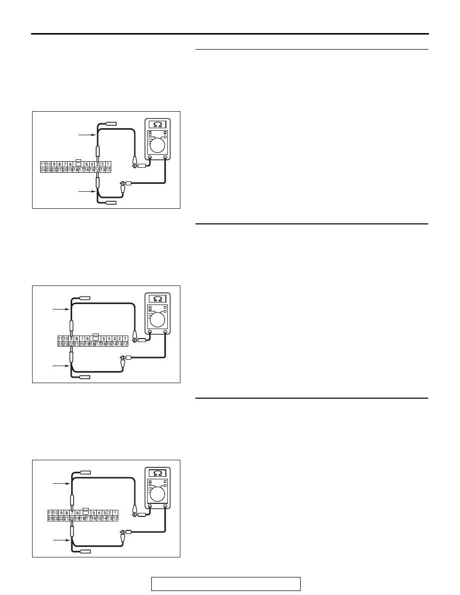
STEP 26. Check the wiring harness between joint 
connector (CAN1) C-105 and combination meter connector 
C-04 for line-to-line short. Measure the resistance at joint 
connector (CAN1) C-105.
(1) Disconnect joint connector (CAN1), and check that there is 

continuity at the harness side of joint connector (CAN1).

(2) Check that there is continuity between joint connector 

(CAN1) terminals 3 and 14.

OK: No continuity

Q: Is the check result normal?

YES (vehicles with KOS) : Go to Step 27.
YES (vehicles with WCM) : Go to Step 28.
NO (vehicles with KOS or WCM) : Go to Step 48.

STEP 27. Check the wiring harness between joint 
connector (CAN1) C-105 and KOS-ECU connector C-05 for 
line-to-line short. Measure the resistance at joint 
connector (CAN1) C-105.
(1) Disconnect joint connector (CAN1), and check that there is 

continuity at the harness side of joint connector (CAN1).

(2) Check that there is continuity between joint connector 

(CAN1) terminals 9 and 22.

OK: No continuity

Q: Is the check result normal?

YES : Go to Step 29.
NO :  Go to Step 49.

STEP 28. Check the wiring harness between joint 
connector (CAN1) C-105 and WCM connector C-07 for 
line-to-line short. Measure the resistance at joint 
connector (CAN1) C-105.
(1) Disconnect joint connector (CAN1), and check that there is 

continuity at the harness side of joint connector (CAN1).

(2) Check that there is continuity between joint connector 

(CAN1) terminals 7 and 20.

OK: No continuity

Q: Is the check result normal?

YES : Go to Step 29.
NO :  Go to Step 50.

AC709707

Harness side: C-105

CR

TEST 
HARNESS

TEST 
HARNESS

AC709707

Harness side: C-105

CS

TEST 
HARNESS

TEST 
HARNESS

AC709707

Harness side: C-105

CT

TEST 
HARNESS

TEST 
HARNESS

DIAGNOSIS

TSB Revision

CONTROLLER AREA NETWORK (CAN)

54C-238

STEP 29. Check the wiring harness between joint 
connector (CAN1) C-105 and SRS-ECU connector C-37 for 
line-to-line short. Measure the resistance at joint 
connector (CAN1) C-105.
(1) Disconnect joint connector (CAN1), and check that there is 

continuity at the harness side of joint connector (CAN1).

(2) Check that there is continuity between joint connector 

(CAN1) terminals 8 and 21.

OK: No continuity

Q: Is the check result normal?

YES : Go to Step 30.
NO :  Go to Step 51.

STEP 30. Check the wiring harness between joint 
connector (CAN1) C-105 and occupant classification-ECU 
connector D-39-2 for line-to-line short. Measure the 
resistance at joint connector (CAN1) C-105.
(1) Disconnect joint connector (CAN1), and check that there is 

continuity at the harness side of joint connector (CAN1).

(2) Check that there is continuity between joint connector 

(CAN1) terminals 11 and 24.

OK: No continuity

Q: Is the check result normal?

YES (vehicles without hands free system) : Go to Step 

32.

YES (vehicles with hands free system) : Go to Step 31.
NO  :  Go to Step 52.

STEP 31. Check the wiring harness between joint 
connector (CAN1) C-105 and hands free module connector 
C-11 for line-to-line short. Measure the resistance at joint 
connector (CAN1) C-105.
(1) Disconnect joint connector (CAN1), and check that there is 

continuity at the harness side of joint connector (CAN1).

(2) Check that there is continuity between joint connector 

(CAN1) terminals 10 and 23.

OK: No continuity

Q: Is the check result normal?

YES : Go to Step 32.
NO :  Go to Step 53.

AC709707

Harness side: C-105

CU

TEST 
HARNESS

TEST 
HARNESS

AC709707

Harness side: C-105

CV

TEST 
HARNESS

TEST 
HARNESS

AC709707

Harness side: C-105

CW

TEST 
HARNESS

TEST 
HARNESS

DIAGNOSIS

TSB Revision

CONTROLLER AREA NETWORK (CAN)

54C-239

STEP 32. Check the wiring harness between joint 
connector (CAN1) C-105 and A/C-ECU connector C-22 
<vehicles with A/C> or heater control unit connector C-53 
<vehicles without A/C> for line-to-line short. Measure the 
resistance at joint connector (CAN1) C-105.
(1) Disconnect joint connector (CAN1), and check that there is 

continuity at the harness side of joint connector (CAN1).

(2) Check that there is continuity between joint connector 

(CAN1) terminals 1 and 12.

OK: No continuity

Q: Is the check result normal?

YES (vehicles without MMCS) : Go to Step 33.
YES (vehicles with MMCS) : Go to Step 34.
NO  :  Go to Step 54.

STEP 33. Check the wiring harness between joint 
connector (CAN1) C-105 and radio and CD player or CD 
changer connector C-107 for line-to-line short. Measure 
the resistance at joint connector (CAN1) C-105.
(1) Disconnect joint connector (CAN1), and check that there is 

continuity at the harness side of joint connector (CAN1).

(2) Check that there is continuity between joint connector 

(CAN1) terminals 5 and 16.

OK: No continuity

Q: Is the check result normal?

YES (vehicles without satellite radio) : Go to Step 36.
YES (vehicles with satellite radio) : Go to Step 35.
NO  :  Go to Step 55.

STEP 34. Check the wiring harness between joint 
connector (CAN1) C-105 and CAN box unit connector C-15 
for line-to-line short. Measure the resistance at joint 
connector (CAN1) C-105.
(1) Disconnect joint connector (CAN1), and check that there is 

continuity at the harness side of joint connector (CAN1).

(2) Check that there is continuity between joint connector 

(CAN1) terminals 5 and 16.

OK: No continuity

Q: Is the check result normal?

YES (vehicles without satellite radio) : Go to Step 36.
YES (vehicles with satellite radio) : Go to Step 35.
NO  :  Go to Step 56.

AC709707

Harness side: C-105

CX

TEST 
HARNESS

TEST 
HARNESS

AC709707

Harness side: C-105

CY

TEST 
HARNESS

TEST 
HARNESS

AC709707

Harness side: C-105

CY

TEST 
HARNESS

TEST 
HARNESS

DIAGNOSIS

TSB Revision

CONTROLLER AREA NETWORK (CAN)

54C-240

STEP 35. Check the wiring harness between joint 
connector (CAN1) C-105 and satellite radio tuner 
connector C-18 for line-to-line short. Measure the 
resistance at joint connector (CAN1) C-105.
(1) Disconnect joint connector (CAN1), and check that there is 

continuity at the harness side of joint connector (CAN1).

(2) Check that there is continuity between joint connector 

(CAN1) terminals 2 and 13.

OK: No continuity

Q: Is the check result normal?

YES : Go to Step 36.
NO :  Go to Step 57.

STEP 36. Check the wiring harness between joint 
connector (CAN1) C-105 and EATCS-ECU connector C-301 
for line-to-line short. Measure the resistance at joint 
connector (CAN1) C-105.
(1) Disconnect joint connector (CAN1) and ETACS-ECU 

connector C-301, and check that there is continuity at the 
harness side of joint connector (CAN1).

(2) Check that there is continuity between joint connector 

(CAN1) terminals 6 and 19.

OK: No continuity

Q: Is the check result normal?

YES : Go to Step 58.
NO :  Repair the wiring harness between joint connector 

(CAN1) C-105 and ETACS-ECU connector C-301.

AC709707

Harness side: C-105

CZ

TEST 
HARNESS

TEST 
HARNESS

AC709707

Harness side: C-105

DA

TEST 
HARNESS

TEST 
HARNESS


Content   ..  51  52  53  54   ..