Mitsubishi Lancer Evolution X. Manual - part 35


  Index      Mitsubishi     Mitsubishi Lancer Evolution X GS41EVO - service repair manual 2008 year


Search            


Content   ..  33  34  35  36   ..


Mitsubishi Lancer Evolution X. Manual - part 35


DIAGNOSIS

TSB Revision

CONTROLLER AREA NETWORK (CAN)

54C-165

DIAGNOSIS

Required Special Tools:

• MB991223: Harness Set
• MB992006: Extra Fine Probe

STEP 1. Check the wiring harness between ETACS-ECU 
connector C-301 and body ground for a short to power 
supply. Measure the voltage at ETACS-ECU connector 
C-301.

CAUTION

A digital multimeter should be used. For details refer to 

P.54C-7

.

CAUTION

The test wiring harness should be used. For details refer to 

P.54C-7

.

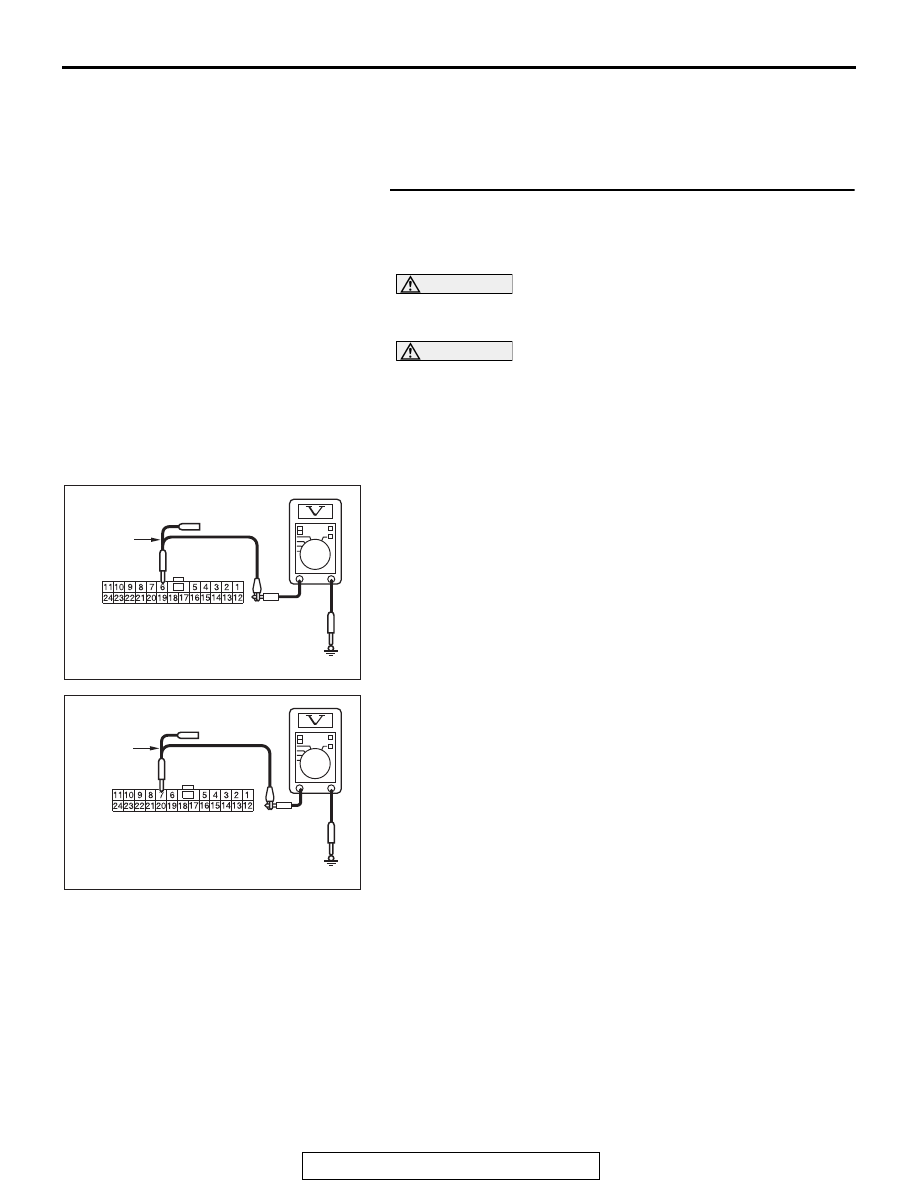
(1) Disconnect ETACS-ECU connector C-301, and measure 

the voltage at the wiring harness side of ETACS-ECU 
connector.

(2) Turn the ignition switch to the ON position.
(3) Measure the voltage between ETACS-ECU connector 

terminal 6 and body ground.

OK: 4.7 V or less

(4) Measure the voltage between ETACS-ECU connector 

terminal 7 and body ground.

OK: 4.7 V or less

Q: Do all the voltages measure 4.7 V or less?

YES : Go to Step 2.
NO :  Go to Step 13.

AC608178

TEST 
HARNESS

Harness side: C-301

AL

AC608178

TEST 
HARNESS

Harness side: C-301

AM

DIAGNOSIS

TSB Revision

CONTROLLER AREA NETWORK (CAN)

54C-166

STEP 2. Check the wiring harness between joint connector 
(CAN1) C-105 and combination meter connector C-04 for a 
short to ground. Measure the resistance at joint connector 
(CAN1) C-105.
(1) Disconnect joint connector (CAN1), and measure the 

resistance at the wiring harness side of joint connector 
(CAN1).

(2) Measure the resistance between joint connector (CAN1) 

terminal 3 and body ground.

OK: 1 kΩ or more

(3) Measure the resistance between joint connector (CAN1) 

terminal 14 and body ground.

OK: 1 kΩ or more

Q: Do all the resistances measure 1 kΩ or more?

YES <vehicles with KOS> : Go to Step 3.
YES <vehicles with WCM> : Go to Step 4.
NO (vehicles with KOS or WCM) : Go to Step 24.

AC608179

TEST 
HARNESS

Harness side: C-105

BY

AC608179

Harness side: C-105

BZ

TEST 
HARNESS

DIAGNOSIS

TSB Revision

CONTROLLER AREA NETWORK (CAN)

54C-167

STEP 3. Check the wiring harness between joint connector 
(CAN1) C-105 and KOS-ECU connector C-05 for a short to 
ground. Measure the resistance at joint connector (CAN1) 
C-105.
(1) Disconnect joint connector (CAN1), and measure the 

resistance at the wiring harness side of joint connector 
(CAN1).

(2) Measure the resistance between joint connector (CAN1) 

terminal 9 and body ground.

OK: 1 kΩ or more

(3) Measure the resistance between joint connector (CAN1) 

terminal 22 and body ground.

OK: 1 kΩ or more

Q: Do all the resistances measure 1 kΩ or more?

YES : Go to Step 5.
NO :  Go to Step 25.

AC608179

TEST 
HARNESS

Harness side: C-105

CA

AC608179

Harness side: C-105

CB

TEST 
HARNESS

DIAGNOSIS

TSB Revision

CONTROLLER AREA NETWORK (CAN)

54C-168

STEP 4. Check the wiring harness between joint connector 
(CAN1) C-105 and WCM connector C-07 for a short to 
ground. Measure the resistance at joint connector (CAN1) 
C-105.
(1) Disconnect joint connector (CAN1), and measure the 

resistance at the wiring harness side of joint connector 
(CAN1).

(2) Measure the resistance between joint connector (CAN1) 

terminal 7 and body ground.

OK: 1 kΩ or more

(3) Measure the resistance between joint connector (CAN1) 

terminal 20 and body ground.

OK: 1 kΩ or more

Q: Do all the resistances measure 1 kΩ or more?

YES : Go to Step 5.
NO :  Go to Step 26.

AC608179

TEST 
HARNESS

Harness side: C-105

CC

AC608179

Harness side: C-06

CD

TEST 
HARNESS


Content   ..  33  34  35  36   ..