Mitsubishi Lancer Evolution X. Manual - part 32


  Index      Mitsubishi     Mitsubishi Lancer Evolution X GS41EVO - service repair manual 2008 year


Search            


Content   ..  30  31  32  33   ..


Mitsubishi Lancer Evolution X. Manual - part 32


DIAGNOSIS

TSB Revision

CONTROLLER AREA NETWORK (CAN)

54C-153

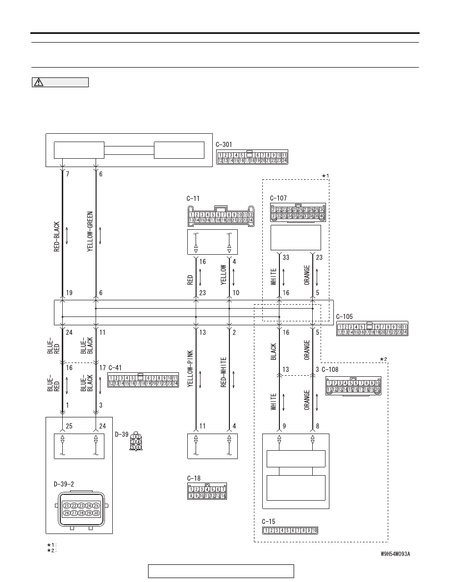
DIAGNOSTIC ITEM 22: Diagnose when the scan tool cannot receive the data sent by satellite radio 
tuner.

CAUTION

When servicing a CAN bus line, ground yourself by touching a metal object such as an unpainted 
water pipe. If you fail to do so, a component connected to the CAN bus line may be damaged.

CAN-B Communication Circuit

ETACS-ECU

INTERFACE 
CIRCUIT

INTERFACE 
CIRCUIT

CAN DRIVE 
CIRCUIT

HANDS FREE 
MODULE

OCCUPANT 
CLASSIFICATION-
ECU

SATELLITE 
RADIO TUNER

RADIO AND CD
PLAYER

NOTE

VEHICLES WITHOUT MITSUBISHI MULTI-COMMUNICATION SYSTEM (MMCS)
VEHICLES WITH MITSUBISHI MULTI-COMMUNICATION SYSTEM (MMCS)

CAN 
TRANSCEIVER 
CIRCUIT

CAN BOX UNIT

JOINT CONNECTOR 
(CAN1)

FRONT SEAT 
ASSEMBLY (LH)

DIAGNOSIS

TSB Revision

CONTROLLER AREA NETWORK (CAN)

54C-154

.

FUNCTION

If the scan tool MB991958 cannot communicate with 
the satellite radio tuner, this diagnosis result will be 
set.

.

TROUBLE JUDGMENT CONDITIONS

If a communication flag is not set for the satellite 
radio tuner, the ETACS-ECU determines that there is 
a failure.

.

TROUBLESHOOTING HINTS

• Malfunction of the connector [joint connector 

(CAN1), satellite radio tuner connector improp-
erly connected]

• Malfunction of the wiring harness [open circuit 

between the satellite radio tuner connector and 
the joint connector (CAN1), power supply circuit 
to the satellite radio tuner]

• Malfunction of the satellite radio tuner

DIAGNOSIS

Required Special Tools:

• MB991223: Harness Set
• MB992006: Extra Fine Probe

STEP 1. Check joint connector (CAN1) C-105 and satellite 
radio tuner connector C-18 for loose, corroded or 
damaged terminals, or terminals pushed back in the 
connector.

CAUTION

The strand end of the twisted wire should be within 10 cm 
(4 inches) from the connector. For details refer to 

P.54C-7

.

Q: Are joint connector (CAN1) C-105 and satellite radio 

tuner connector C-18 in good condition?
YES : 
Go to Step 2.
NO :  Repair the damaged parts.

AC708951BX

Connector: C-18

AC708950

Connector: C-105

BL

DIAGNOSIS

TSB Revision

CONTROLLER AREA NETWORK (CAN)

54C-155

STEP 2. Check the wiring harness between joint connector 
(CAN1) C-105 and satellite radio tuner connector C-18 for 
open circuit.

CAUTION

Strictly observe the specified wiring harness repair proce-
dure. For details refer to 

P.54C-7

.

(1) Disconnect joint connector (CAN1) C-105 and satellite radio 

tuner connector C-18, and check the wiring harness.

(2) Check the wiring harness between joint connector (CAN1) 

C-105 (terminal 2) and satellite radio tuner connector C-18 
(terminal 4)

OK: Continuity exists (2 Ω or less)

(3) Check the wiring harness between joint connector (CAN1) 

C-105 (terminal 13) and satellite radio tuner connector C-18 
(terminal 11)

OK: Continuity exists (2 Ω or less)

Q: Is the wiring harness between joint connector (CAN1) 

C-105 and satellite radio tuner connector C-18 in good 
condition?
YES : 
Check the power supply circuit of the satellite radio 

tuner. Refer to GROUP 54A, Diagnosis <Satellite 
radio tuner> 

P.54A-617

.

NO :  Repair the wiring harness between joint connector 

(CAN1) C-105 and satellite radio tuner connector 
C-18.

AC709707 CJ

Harness side: C-105

Harness side: C-18

TEST 
HARNESS

TEST 
HARNESS

AC709707 CK

Harness side: C-105

Harness side: C-18

TEST 
HARNESS

TEST HARNESS

DIAGNOSIS

TSB Revision

CONTROLLER AREA NETWORK (CAN)

54C-156

DIAGNOSTIC ITEM 23: Diagnose when the scan tool cannot receive the data sent by hands free 
module.

CAUTION

When servicing a CAN bus line, ground yourself by touching a metal object such as an unpainted 
water pipe. If you fail to do so, a component connected to the CAN bus line may be damaged.

CAN-B Communication Circuit

ETACS-ECU

INTERFACE 
CIRCUIT

INTERFACE 
CIRCUIT

CAN DRIVE 
CIRCUIT

HANDS FREE 
MODULE

OCCUPANT 
CLASSIFICATION-
ECU

SATELLITE 
RADIO TUNER

RADIO AND CD
PLAYER

NOTE

VEHICLES WITHOUT MITSUBISHI MULTI-COMMUNICATION SYSTEM (MMCS)
VEHICLES WITH MITSUBISHI MULTI-COMMUNICATION SYSTEM (MMCS)

CAN 
TRANSCEIVER 
CIRCUIT

CAN BOX UNIT

JOINT CONNECTOR 
(CAN1)

FRONT SEAT 
ASSEMBLY (LH)


Content   ..  30  31  32  33   ..