Mitsubishi Lancer Evolution X. Manual - part 31
DIAGNOSIS
TSB Revision
CONTROLLER AREA NETWORK (CAN)
54C-149
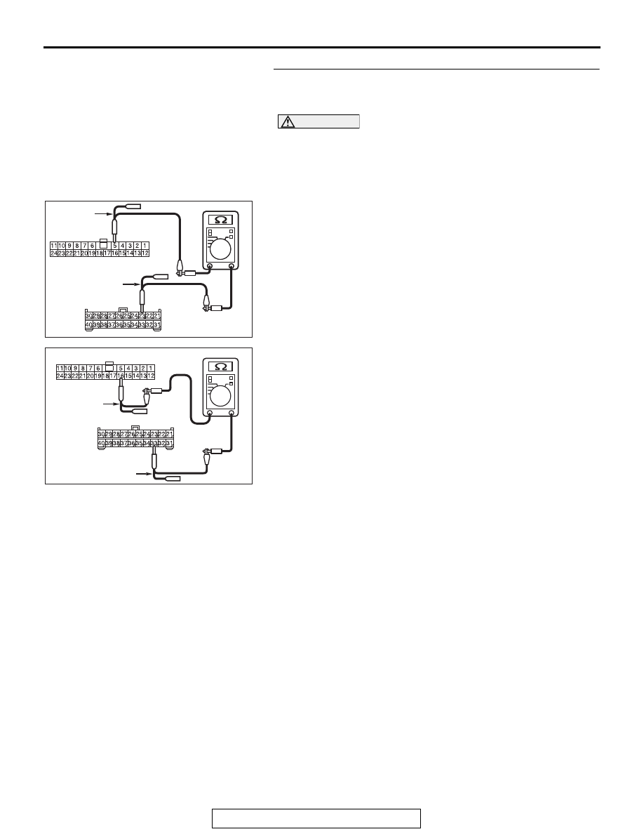
STEP 2. Check the wiring harness between joint connector
(CAN1) C-105 and radio and CD player or CD changer
connector C-107 for open circuit.
CAUTION
Strictly observe the specified wiring harness repair proce-
dure. For details refer to
(1) Disconnect joint connector (CAN1) C-105 and radio and CD
player or CD changer connector C-107, and check the
wiring harness.
(2) Check the wiring harness between joint connector (CAN1)
C-105 (terminal 5) and radio and CD player or CD changer
connector C-107 (terminal 23)
OK: Continuity exists (2 Ω or less)
(3) Check the wiring harness between joint connector (CAN1)
C-105 (terminal 16) and radio and CD player or CD changer
connector C-107 (terminal 33)
OK: Continuity exists (2 Ω or less)
Q: Is the wiring harness between joint connector (CAN1)
C-105 and radio and CD player or CD changer connector
C-107 in good condition?
YES : Check the power supply circuit of the radio and CD
player or CD changer. Refer to GROUP 54A, radio
and CD player − Diagnosis <radio and CD player>
.
NO : Repair the wiring harness between joint connector
(CAN1) C-105 and radio and CD player or CD
changer connector C-107.
AC709707
AC709707 CF
Harness side: C-105
TEST
HARNESS
Harness side: C-107
TEST HARNESS
AC709707 CG
Harness side: C-105
Harness side: C-107
TEST
HARNESS
TEST HARNESS