Mitsubishi Lancer Evolution X. Manual - part 5


  Index      Mitsubishi     Mitsubishi Lancer Evolution X GS41EVO - service repair manual 2008 year


Search            


Content   ..  3  4  5  6   ..


Mitsubishi Lancer Evolution X. Manual - part 5


DIAGNOSIS

TSB Revision

CONTROLLER AREA NETWORK (CAN)

54C-45

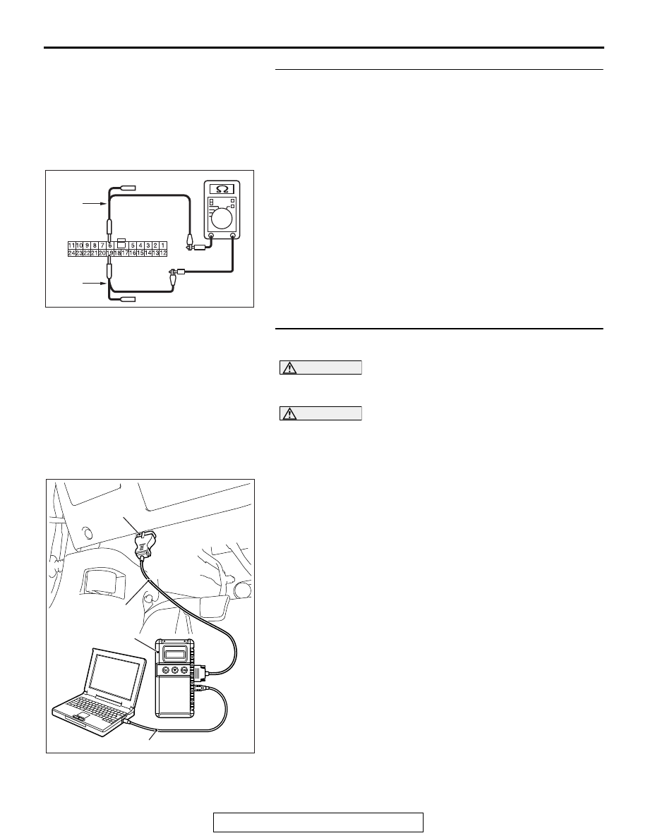
STEP 13. Check the wiring harness between joint 
connector (CAN2) C-104 and ETACS-ECU connector C-301 
for line-to-line short. Measure the resistance at joint 
connector (CAN2) C-104.
(1) Disconnect joint connector (CAN2) and ETACS-ECU 

connector, and check that there is continuity at the harness 
side of joint connector (CAN2).

(2) Check that there is continuity between joint connector 

(CAN2) terminals 6 and 19.

OK: No continuity

Q: Is the check result normal?

YES : Go to Step 18.
NO :  Repair the wiring harness between ETACS-ECU 

connector C-301 and joint connector (CAN2) C-104.

STEP 14. Using scan tool MB991958, diagnose the CAN 
bus line. (checking the ASC-ECU for internal short)

CAUTION

Strictly observe the specified wiring harness repair proce-
dure. For details refer to 

P.54C-7

.

CAUTION

To prevent damage to scan tool MB991958, always turn the 
ignition switch to the "LOCK" (OFF) position before con-
necting or disconnecting scan tool MB991958.
(1) Disconnect ASC-ECU connector A-05.
(2) Connect scan tool MB991958 to the data link connector.
(3) Turn the ignition switch to the "ON" position.

AC709707

Harness side: C-104

AI

TEST 
HARNESS

TEST 
HARNESS

AC608435

Data link connector

MB991827

MB991824

MB991910

AB

DIAGNOSIS

TSB Revision

CONTROLLER AREA NETWORK (CAN)

54C-46

(4) Diagnose CAN bus lines, and check if the scan tool 

MB991958 screen is as shown in the figure.

OK: The display of the scan tool MB991958 is as 
shown in the figure.

Q: Does scan tool MB991958 screen correspond to the 

illustration?
YES : 
Repair the wiring harness between ASC-ECU 

connector A-05 and joint connector (CAN3) C-127.

NO :  Check ASC-ECU connector A-05, and repair if 

necessary. If the ASC-ECU connector is in good 
condition, replace the ASC-ECU.

STEP 15. Using scan tool MB991958, diagnose the CAN 
bus line. (checking the ECM for internal short)

CAUTION

Strictly observe the specified wiring harness repair proce-
dure. For details refer to 

P.54C-7

.

CAUTION

To prevent damage to scan tool MB991958, always turn the 
ignition switch to the "LOCK" (OFF) position before con-
necting or disconnecting scan tool MB991958.
(1) Disconnect ECM connector B-10.

AC709542 AC

: Red section on screen

M.U.T.

J/C (3)

J/C (2)

KOS/WCM

SRS

A/C

AUDIO

MMCS

Sat Radio

HFM

OCM

METER

ASC

ENGINE

J/C (1)

ETACS

<M/T>

SAS

S-AWC

AC709543 AC

: Red section on screen

M.U.T.

J/C (3)

J/C (2)

KOS/WCM

SRS

A/C

AUDIO

MMCS

Sat Radio

HFM

OCM

METER

ASC

LEVER

J/C (1)

ETACS

<TC-SST>

SAS

S-AWC

J/C (4)

TC-SST

ENGINE

DIAGNOSIS

TSB Revision

CONTROLLER AREA NETWORK (CAN)

54C-47

(2) Connect scan tool MB991958 to the data link connector.
(3) Turn the ignition switch to the "ON" position.

(4) Diagnose CAN bus lines, and check if the scan tool 

MB991958 screen is as shown in the figure.

OK: The display of the scan tool MB991958 is as 
shown in the figure.

Q: Does scan tool MB991958 screen correspond to the 

illustration?
YES : 
Repair the wiring harness between ECM connector 

B-10 and joint connector (CAN3) C-127 <M/T>, or 
check intermediate connector A-13, and repair if 
necessary. If the intermediate connector is in good 
condition, repair the wiring harness between ECM 
connector B-10 and joint connector (CAN4) A-14 
<TC-SST>.

NO :  Check ECM connector B-10, and repair if necessary. 

If the ECM connector is in good condition, replace the 
ECM.

AC608435

Data link connector

MB991827

MB991824

MB991910

AB

AC709542 AC

: Red section on screen

M.U.T.

J/C (3)

J/C (2)

KOS/WCM

SRS

A/C

AUDIO

MMCS

Sat Radio

HFM

OCM

METER

ASC

ENGINE

J/C (1)

ETACS

<M/T>

SAS

S-AWC

AC709543 AC

: Red section on screen

M.U.T.

J/C (3)

J/C (2)

KOS/WCM

SRS

A/C

AUDIO

MMCS

Sat Radio

HFM

OCM

METER

ASC

LEVER

J/C (1)

ETACS

<TC-SST>

SAS

S-AWC

J/C (4)

TC-SST

ENGINE

DIAGNOSIS

TSB Revision

CONTROLLER AREA NETWORK (CAN)

54C-48

STEP 16. Using scan tool MB991958, diagnose the CAN 
bus line. (checking the shift lever for internal short)

CAUTION

Strictly observe the specified wiring harness repair proce-
dure. For details refer to 

P.54C-7

.

CAUTION

To prevent damage to scan tool MB991958, always turn the 
ignition switch to the "LOCK" (OFF) position before con-
necting or disconnecting scan tool MB991958.
(1) Disconnect shift lever connector C-27.
(2) Connect scan tool MB991958 to the data link connector.
(3) Turn the ignition switch to the "ON" position.

(4) Diagnose CAN bus lines, and check if the scan tool 

MB991958 screen is as shown in the figure.

OK: The display of the scan tool MB991958 is as 
shown in the figure.

Q: Does scan tool MB991958 screen correspond to the 

illustration?
YES : 
Repair the wiring harness between shift lever 

connector C-27 and joint connector (CAN3) C-127.

NO :  Check shift lever connector C-27, and repair if 

necessary. If the shift lever connector is in good 
condition, replace the shift lever.

AC608435

Data link connector

MB991827

MB991824

MB991910

AB

AC709542 AC

: Red section on screen

M.U.T.

J/C (3)

J/C (2)

KOS/WCM

SRS

A/C

AUDIO

MMCS

Sat Radio

HFM

OCM

METER

ASC

ENGINE

J/C (1)

ETACS

<M/T>

SAS

S-AWC

AC709543 AC

: Red section on screen

M.U.T.

J/C (3)

J/C (2)

KOS/WCM

SRS

A/C

AUDIO

MMCS

Sat Radio

HFM

OCM

METER

ASC

LEVER

J/C (1)

ETACS

<TC-SST>

SAS

S-AWC

J/C (4)

TC-SST

ENGINE


Content   ..  3  4  5  6   ..