Mitsubishi Lancer Evolution X. Manual - part 3


  Index      Mitsubishi     Mitsubishi Lancer Evolution X GS41EVO - service repair manual 2008 year


Search            


Content   ..  1  2  3  4  ..


Mitsubishi Lancer Evolution X. Manual - part 3


DIAGNOSIS

TSB Revision

CONTROLLER AREA NETWORK (CAN)

54C-37

DIAGNOSIS

Required Special Tools:

• MB991223: Harness Set
• MB992006: Extra Fine Probe
• MB991958: Scan Tool (M.U.T.-III Sub Assembly)

• MB991824: Vehicle Communication Interface (V.C.I.)
• MB991827: M.U.T.-III USB Cable
• MB991910: M.U.T.-III Main Harness A

• MB992110: Power plant ECU check harness
• MB991997: ASC Check Harness

STEP 1. Check joint connector (CAN2) C-104, joint 
connector (CAN3) C-127 and joint connector (CAN4) A-14 
<TC-SST> for loose, corroded or damaged terminals, or 
terminals pushed back in the connector.

CAUTION

The strand end of the twisted wire should be within 10 cm 
(4 inches) from the connector. For details refer to 

P.54C-7

.

Q: Are joint connector (CAN2) C-104, joint connector 

(CAN3) C-127 and joint connector (CAN4) A-14 in good 
condition?
YES : 
Go to Step 2.
NO :  Repair the damaged parts.

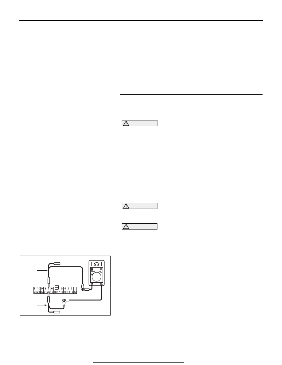
STEP 2. Check the wiring harness between joint connector 
(CAN2) C-104 and steering wheel senor connector C-209 
for line-to-line short. Measure the resistance at joint 
connector (CAN2) C-104.

CAUTION

A digital multimeter should be used. For details refer to 

P.54C-7

.

CAUTION

The test wiring harness should be used. For details refer to 

P.54C-7

.

(1) Disconnect joint connector (CAN2), and check that there is 

continuity at the harness side of joint connector (CAN2).

(2) Check that there is continuity between joint connector 

(CAN2) terminals 7 and 20.

OK: No continuity

Q: Is the check result normal?

YES : Go to Step 3.
NO :  Go to Step 11.

AC709707

Harness side: C-104

AG

TEST 
HARNESS

TEST 
HARNESS

DIAGNOSIS

TSB Revision

CONTROLLER AREA NETWORK (CAN)

54C-38

STEP 3. Check the wiring harness between joint connector 
(CAN2) C-104 and S-AWC-ECU connector C-46 for 
line-to-line short. Measure the resistance at joint 
connector (CAN2) C-104.

CAUTION

A digital multimeter should be used. For details refer to 

P.54C-7

.

CAUTION

The test wiring harness should be used. For details refer to 

P.54C-7

.

(1) Disconnect joint connector (CAN2), and check that there is 

continuity at the harness side of joint connector (CAN2).

(2) Check that there is continuity between joint connector 

(CAN2) terminals 5 and 16.

OK: No continuity

Q: Is the check result normal?

YES : Go to Step 4.
NO :  Go to Step 12.

STEP 4. Check the wiring harness between joint connector 
(CAN2) C-104 and ETACS-ECU connector C-301 for 
line-to-line short. Measure the resistance at joint 
connector (CAN2) C-104.

CAUTION

A digital multimeter should be used. For details refer to 

P.54C-7

.

CAUTION

The test wiring harness should be used. For details refer to 

P.54C-7

.

(1) Disconnect joint connector (CAN2), and check that there is 

continuity at the harness side of joint connector (CAN2).

(2) Check that there is continuity between joint connector 

(CAN2) terminals 6 and 19.

OK: 120 ± 20 Ω

Q: Is the check result normal?

YES : Go to Step 5.
NO :  Go to Step 13.

AC709707

Harness side: C-104

AH

TEST 
HARNESS

TEST 
HARNESS

AC709707

Harness side: C-104

AI

TEST 
HARNESS

TEST 
HARNESS

DIAGNOSIS

TSB Revision

CONTROLLER AREA NETWORK (CAN)

54C-39

STEP 5. Check the wiring harness between joint connector 
(CAN3) C-127 and ASC-ECU connector A-05 for line-to-line 
short. Measure the resistance at joint connector (CAN3) 
C-127.

CAUTION

A digital multimeter should be used. For details refer to 

P.54C-7

.

CAUTION

The test wiring harness should be used. For details refer to 

P.54C-7

.

(1) Disconnect joint connector (CAN3), and check that there is 

continuity at the harness side of joint connector (CAN3).

(2) Check that there is continuity between joint connector 

(CAN3) terminals 6 and 19.

OK: No continuity

Q: Is the check result normal?

YES <M/T> : Go to Step 6.
YES <TC-SST> : Go to Step 7.
NO  :  Go to Step 14.

STEP 6. Check the wiring harness between joint connector 
(CAN3) C-127 and ECM connector B-10 <M/T> for 
line-to-line short. Measure the resistance at joint 
connector (CAN3) C-127.

CAUTION

A digital multimeter should be used. For details refer to 

P.54C-7

.

CAUTION

The test wiring harness should be used. For details refer to 

P.54C-7

.

(1) Disconnect joint connector (CAN3), and check that there is 

continuity at the harness side of joint connector (CAN3).

(2) Check that there is continuity between joint connector 

(CAN3) terminals 4 and 15.

OK: 120 ± 20 Ω

Q: Is the check result normal?

YES : Check intermediate connector C-131, and repair if 

necessary. If the intermediate connector is in good 
condition, repair the wiring harness between joint 
connector (CAN2) C-104 and joint connector (CAN3) 
C-127.

NO :  Go to Step 15.

AC709707

Harness side: C-127

AJ

TEST 
HARNESS

TEST 
HARNESS

AC709707

Harness side: C-127

AK

TEST 
HARNESS

TEST 
HARNESS

DIAGNOSIS

TSB Revision

CONTROLLER AREA NETWORK (CAN)

54C-40

STEP 7. Check the wiring harness between joint connector 
(CAN3) C-127 and shift lever connector for line-to-line 
short. Measure the resistance at joint connector (CAN3) 
C-127.

CAUTION

A digital multimeter should be used. For details refer to 

P.54C-7

.

CAUTION

The test wiring harness should be used. For details refer to 

P.54C-7

.

(1) Disconnect joint connector (CAN3), and check that there is 

continuity at the harness side of joint connector (CAN3).

(2) Check that there is continuity between joint connector 

(CAN3) terminals 7 and 20.

OK: No continuity

Q: Is the check result normal?

YES : Go to Step 8.
NO :  Go to Step 16.

STEP 8. Check the wiring harness between joint connector 
(CAN4) A-14 and ECM connector B-10 <TC-SST> for 
line-to-line short. Measure the resistance at joint 
connector (CAN4) A-14.

CAUTION

A digital multimeter should be used. For details refer to 

P.54C-7

.

CAUTION

The test wiring harness should be used. For details refer to 

P.54C-7

.

(1) Disconnect joint connector (CAN4), and check that there is 

continuity at the harness side of joint connector (CAN4).

(2) Check that there is continuity between joint connector 

(CAN4) terminals 7 and 20.

OK: No continuity

Q: Is the check result normal?

YES : Go to Step 9.
NO :  Go to Step 15.

AC709707

Harness side: C-127

AL

TEST 
HARNESS

TEST 
HARNESS

AC709707

Harness side: A-14

AM

TEST 
HARNESS

TEST 
HARNESS


Content   ..  1  2  3  4  ..