Mitsubishi Lancer Evolution IX. Manual - part 570
AC504564
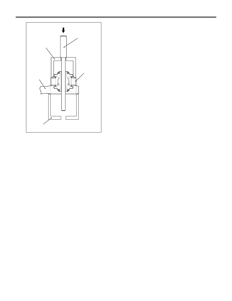
MB990651
MB991576
Lower arm
assembly
MB991816
AB
Outer tube
LOWER ARM
FRONT SUSPENSION
33-13
3. Use special tools to press in the bushing until its
outer tube is flush with the lower arm assembly
surface.