Mitsubishi Lancer Evolution IX. Manual - part 244


  Index      Mitsubishi     Mitsubishi Lancer Evolution IX - service repair manual


Search            


Content   ..  242  243  244  245   ..


Mitsubishi Lancer Evolution IX. Manual - part 244


SYMPTOM PROCEDURES

SMART WIRING SYSTEM (SWS) USING SWS MONITOR

54C-235

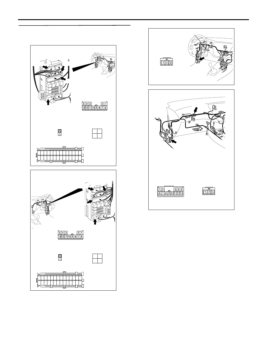
Step 8. Check the wiring harness between C-219 
rear fog lamp relay connector (terminal Nos.3 
and 4) and the battery.

NOTE: 

Prior to the wiring harness inspection, check interme-
diate connector C-126, joint connector C-21 <RH 
drive vehicles> and junction block connectors C-209, 
C-212 and C-214, and repair if necessary.

• Check the power supply line for open circuit.

Q: Is the check result normal?

YES : 

The trouble can be an intermittent 

malfunction (Refer to GROUP 00 

− How to 

Cope with Intermittent Malfunction 

P.00-5

).

NO : 

Repair the wiring harness.

AC310449

Connectors: C-209, C-212, C-214, C-219

AC

C-219

<LHD>

C-209

Junction block side

3

1

2
4

C-209

Harness side

C-219

C-214

Harness side

21

7

16 15

17

18

20 19

1

2

3

4

5

6

23 22

24

25

28

26

27

9

8

10

11

14

12

13

C-212(B)

C-214

C-212

Harness side

Junction block (front view)

AC310459

Connectors: C-209, C-212, C-214, C-219

AC

C-219

<RHD>

C-209

Junction block side

3

1

2
4

C-209
Harness side

C-219

C-214

Harness side

21

7

16 15

17

18

20 19

1

2

3

4

5

6

23 22

24

25

28

26

27

9

8

10

11

14

12

13

C-212(B)

C-214

C-212
Harness side

Junction block (front view)

AC310446

Connector: C-126

AJ

<LHD>

AC310455

Connectors: C-21, C-126

AD

<RHD>

C-126

C-21

C-126

C-21

Junction block side

SYMPTOM PROCEDURES

SMART WIRING SYSTEM (SWS) USING SWS MONITOR

54C-236

Step 9. Connector check: C-228 ETACS-ECU 
connector

Q: Is the check result normal?

YES : 

Go to Step 10.

NO : 

Repair the defective connector.

Step 10. Check the wiring harness between C-219 
rear fog lamp relay connector terminal No.2 and 
C-228 ETACS-ECU connector terminal No.74.

NOTE: Prior to the wiring harness inspection, check 
junction block connector C-209, and repair if neces-
sary.

• Check the output lines for open circuit.

Q: Is the check result normal?

YES : 

Go to Step 11.

NO : 

Repair the wiring harness.

Step 11. Retest the system.
Check that the rear fog lamps illuminate normally.

Q: Is the check result normal?

YES : 

The trouble can be an intermittent 

malfunction (Refer to GROUP 00 

− How to 

Cope with Intermittent Malfunction 

P.00-5

).

NO : 

Replace the ETACS-ECU.

AC310450

Connector: C-228

AH

Junction block 
(rear view)

Harness side

<LHD>

51

52

53

54

55

56

57

58

59

58 5756 55 54 53 52 51 60

74 7372

71 70 69

AC310461

Harness side

Junction block (rear view)

Connector: C-228

AG

<RHD>

51

52

53

54

55

56

57

58

59

58 5756 55 54 53 52 51 60

74 7372

71 70 69

AC310448

Junction block (front view)

Connector: C-219

AN

<LHD>

Junction block side

3

1

2
4

AC310458

Junction block (front view)

Connector: C-219

AK

<RHD>

Junction block side

3

1

2
4

AC310450

Connector: C-228

AH

Junction block 
(rear view)

Harness side

<LHD>

51

52

53

54

55

56

57

58

59

58 5756 55 54 53 52 51 60

74 7372

71 70 69

AC310461

Harness side

Junction block (rear view)

Connector: C-228

AG

<RHD>

51

52

53

54

55

56

57

58

59

58 5756 55 54 53 52 51 60

74 7372

71 70 69

SYMPTOM PROCEDURES

SMART WIRING SYSTEM (SWS) USING SWS MONITOR

54C-237

INSPECTION PROCEDURE J-2: The rear fog lamp or the rear fog lamp indicator does not illuminate 
normally.

CAUTION

Whenever the ECU is replaced, ensure that the 
input and output signal circuits are normal.

Wire colour code
B : Black     LG : Light green     G : Green     L : Blue     W : White     Y : Yellow     SB : Sky blue
BR : Brown     O : Orange     GR : Gray     R : Red     P : Pink     V : Violet

ETACS-ECU

FUSIBLE
LINK

1

COMBINATION
METER

REAR
COMBINATION
LAMP
(REAR FOG)

REAR
FOG
LAMP
RELAY

Rear Fog Lamp Circuit <LHD>

SYMPTOM PROCEDURES

SMART WIRING SYSTEM (SWS) USING SWS MONITOR

54C-238

COMMENTS ON TROUBLE SYMPTOM

If any of the rear fog lamps do not illuminate, the wir-
ing harness connector(s), the bulb or the fuse may 
be defective or burned out.

POSSIBLE CAUSES

• Burned-out rear fog lamp bulb

• Damaged harness wires and connectors

Wire colour code
B : Black     LG : Light green     G : Green     L : Blue
W : White     Y : Yellow     SB : Sky blue     BR : Brown
O : Orange     GR : Gray     R : Red     P : Pink     V : Violet

COMBINATION
METER

REAR
COMBINATION
LAMP
(REAR FOG)

REAR FOG
LAMP RELAY

ETACS-
ECU

FUSIBLE
LINK

Rear Fog Lamp Circuit <RHD>


Content   ..  242  243  244  245   ..