Mitsubishi Lancer Evolution 8. Manual - part 145


  Index      Mitsubishi     Mitsubishi Lancer Evolution 8 - service repair manual


Search            


Content   ..  143  144  145  146   ..


Mitsubishi Lancer Evolution 8. Manual - part 145


SWS – TROUBLESHOOTING

54B-103

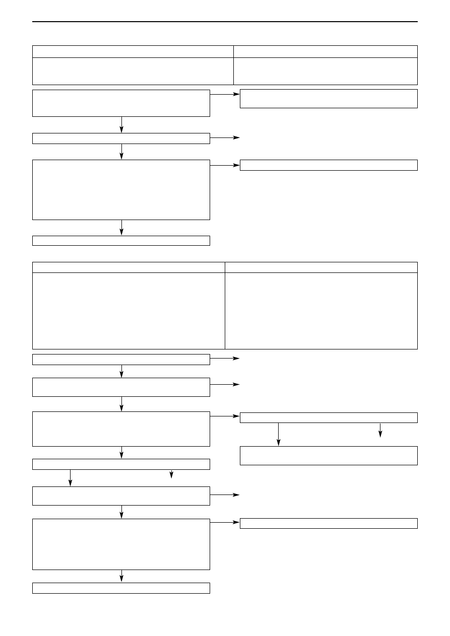
SWS monitor ECU check
Centre display
OK: “OK” is displayed

Check the multi-centre display

Replace the multi-centre display

Check connector C-202

Check the key reminder switch (Chap. 54A Ignition
switch *)

Measure at the Key reminder switch connector C-202
• Detach the connector and measure at the harness side
• Connectivity between 4 & body earth
OK: Connectivity

Check connector C-226

Check the harness between the key reminder switch and
the ETACS-ECU 

SWS monitor service data
ETACS switch data
• Ignition switch: OFF (key inserted)
Item No.

Item Name

Normal state

03

Key reminder SW

ON

OK: Normal state displayed

Transient problem

Check connector C-107

Check the harness between the key reminder switch and
the body earth, and repair

Replace the ETACS-ECU 

To Inspection procedure A-7 No communication with
multi-centre display (p.54B-32)

Transient problem

SWS monitor service data
(Communications data) Centre display
• Ignition switch: ACC
Item No.

Item Name

Normal state

62

Display input

ON

OK: Normal state displayed when audio operating stick is
pressed, except for volume

Inspection procedure R-10

Inspection procedure R-11

Note: 
*: See ’00-5 Lancer Sedia Servicing Manual (No. 1036K00)

Respective switch signals not input for multi-centre display

Probable Cause

If there is a problem in the multi-centre display, then the multi-
centre display input check response signal will cease to be
output to the SWS communications line. 

• Fault in multi-centre display
• Fault in harness or connectors

Key reminder switch signal not input

Probable Cause

The input signal of the key reminder switch is used when
determining the operation of the following functions.
Therefore, if there is a problem in this input signal, then these
functions will not operate correctly.
• Ignition key left in warning function
• Key left in warning function
• Keyless entry
• Ignition key cylinder illumination light
• Interior lights

• Fault in key reminder switch
• Fault in ETACS-ECU 
• Fault in harness or connectors

OK

NG

NG

OK

OK

NG

Repair, Replace

OK

OK

OK

OK

NG

Repair

OK

OK

Repair

Repair

Repair

Replace

OK

NG

NG

NG

NG

NG

NG

SWS – TROUBLESHOOTING

54B-104

Inspection procedure R-12

Check connector C-112

Check the motorised remote control mirror switch (See
Chap 51 – Door mirrors *)

Measure at the Motorised remote control mirror switch
connector C-112
• Detach the connector and measure at the harness side
• Connectivity between 1 & body earth
OK: Connectivity

Check connector C-226

Check the harness between the motorised remote
control mirror switch and the ETACS-ECU 

SWS monitor service data
ETACS switch data
• Ignition switch: ON
• Motorised remote control door mirror (retract/return)
switch: ON
Item No.

Item Name

Normal state

14

Motorised mirror SW

ON

OK: Normal state displayed

Replace the ETACS-ECU 

Check connector C-107

Check the harness between the motorised remote
control mirror switch and the body earth, and repair

Transient problem

Note: 
*: See ’00-5 Lancer Sedia Servicing Manual (No. 1036K00)

Motorised remote control mirror switch (retract / return switch)
signal not input

Probable Cause

The input signal of the motorised remote control mirror switch
(retract / return) switch is used to determine the operation of
the motorised retractable door mirrors, and therefore, if there
is a problem with this signal, the retract/return operation for
the door mirrors will not be possible, even when the motorised
remote control mirror switch is pressed.

∑ Fault in motorised remote control mirror switch
∑ Fault in ETACS-ECU 
∑ Fault in harness or connectors

OK

OK

OK

OK

NG

OK

NG

Repair

Repair

NG

NG

OK

NG

NG

OK

Repair

Repair

Replace

SWS – TROUBLESHOOTING

54B-105

Check connectors
C-14  (Vehicle not fitted with multi-centre display)
C-105 (Vehicle fitted with multi-centre display)

Check the hazard light switch (See Chap 54A Hazard
light switch *)

Check connector C-225

Check the harness between the hazard light switch and
the ETACS-ECU. 

Transient problem

Check connector C-107

Check the harness between the hazard light switch and
the body earth, and repair

Replace the ETACS-ECU 

Measure at the Hazard light switch connector
C-14  (Vehicle not fitted with multi-centre display)
C-105 (Vehicle fitted with multi-centre display)
• Detach the connector and measure at the harness side
• Ignition switch: ON
• Connectivity between 2 & body earth
OK: Connectivity

SWS monitor service data
ETACS switch data
• Ignition switch: OFF
• Hazard light switch : ON
Item No.

Item Name

Normal state

04

Hazard light SW

ON

OK: Normal state displayed

Note: 
*: See ’00-5 Lancer Sedia Servicing Manual (No. 1036K00)

Inspection procedure R-13

Hazard light switch signal not input

Probable Cause

The hazard light switch input signal is used to determine the
operation of the hazard lights, and therefore, if there is a
problem with this signal, then the hazard lights will not light
up. 

• Fault in hazard light switch
• Fault in ETACS-ECU 
• Fault in harness or connectors

OK

OK

OK

OK

OK

OK

NG

NG

NG

NG

OK

NG

NG

NG

Repair

Replace

Repair

Repair

Repair

SWS – TROUBLESHOOTING

54B-106

Inspection procedure R-14

SWS monitor service data
(Communications data) ETACS-ECU
• Driver’s door: Open
Item No.

Item Name

Normal state

32

Front door  SW RH

ON

OK: Normal state displayed

Check the state of installation of the door switch on the
body

To Inspection procedure R-4 Driver’s door switch signal
not input (p.54B-98)

Transient problem

Check the door switch (See Chap. 42 Doors*)

Check the harnesses between the respective door
switches and the ETACS-ECU

Replace the ETACS-ECU 

Check connectors 
(Front passenger door) D-15
(Rear left passenger door) D-09
(Rear right passenger door) D-07

Check connectors 
(Front passenger door) C-29, C-212, C-224
(Rear left passenger door) C-29, C-212, C-224
(Rear right passenger door) C-215, C-224

SWS monitor service data
(Communications data) ETACS
• Doors: Respectively opened and closed
Item No.

Item Name

Normal state

38

Security alarm

ON

OK: Normal state displayed

Note: 
*: See ’00-5 Lancer Sedia Servicing Manual (No. 1036K00)

All door switch signals not input  (except driver’s door)

Probable Cause

Because the input signals from all the door switches are used
to determine the operation of the following functions, these
functions will not work correctly if there is an error in the input
signals.
• Keyless entry system
• Room light
The driver’s door switch is connected internally via the
ETACS-ECU, so it should also be checked that there is no
malfunction in the driver’s door switch input signal.

• Fault in door switch
• Fault in ETACS-ECU 
• Fault in harness or connectors

OK

NG

NG

NG

NG

NG

NG

OK

OK

OK

OK

OK

OK

NG

Repair

Repair

Replace

Repair

Repair


Content   ..  143  144  145  146   ..